Samson Media 6 Mounting And Operating Instructions
Differential pressure meter with lcd/led
Hide thumbs
Also See for Media 6:
- Mounting and operating manual (48 pages) ,
- Original instructions manual (40 pages) ,
- Mounting and operating instructions (42 pages)
Table of Contents

Subscribe to Our Youtube Channel
Related Manuals for Samson Media 6


Summary of Contents for Samson Media 6
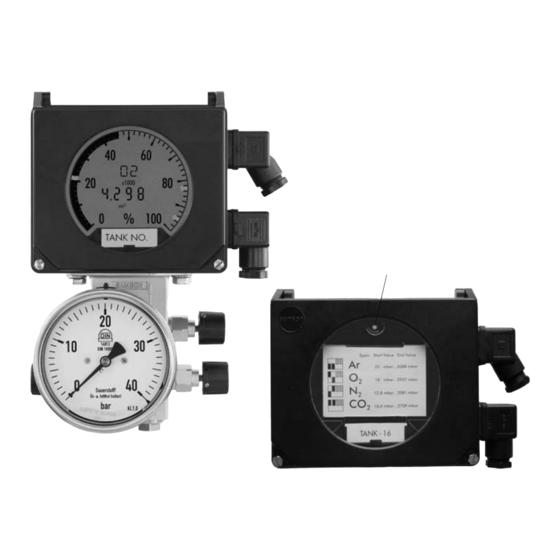
- Page 1 Differential Pressure Meter Media 6 with LCD Media 6 with LED Fig. 1 ⋅ Media 6 with LCD and attached valve block, Media 6 with LED (right) Mounting and Operating Instructions EB 9527-1 EN Firmware A 2.11 (LCD), B 2.11 (LED)
-
Page 2: Table Of Contents
Arrangement of instruments ......10 Media 6 Indicating Unit ......10 Valve block . - Page 3 Make sure that the instrument is only used where temperatures and operat- ing pressure do not exceed the sizing data specified in the order. The Media 6 Differential Pressure Meter is not certified for measuring flammable gases or liquids in Zone 0 areas.
- Page 4 Filling limit during oper- ation on the device independently of the limit switches A 2.10 / B 2.10 A 2.11 / B 2.11 Error code The current output of the Media 6 device is switched to ≥ 3.6 mA EB 9527-1 EN...
- Page 5 Previous version New version EB 9527-1 EN...
-
Page 6: Design And Principle Of Operation
The operating data of Media 6 can The measuring device consists of a dp cell also be uploaded to the memory pen and and an indicating unit. The cell has a downloaded to the device on site. - Page 7 Design and principle of operation Indicating unit with LCD or LED Connector A = 12 to 36 V DC = 4 to 20 mA Min./max. alarm A1 Connector B Min./max. alarm A2 SERIAL INTERFACE µP EEPROM Differential Differential pressure cell 1.1 Measuring diaphragm pressure cell 1.2 Measuring springs...
-
Page 8: Technical Data
Technical data 1.2 Technical data Differential pressure meter Nominal range mbar 1000 1600 2500 3600 Adjustable span mbar Class ± 1.0 % ≤ 250 ≤ 400 ≤ 600 ≤ 1000 ≤ 1600 ≤ 2500 ≤ 3600 from ≥ 125 ≥ 100 ≥... - Page 9 VBG 62 or equivalent regulations until the devices are handed over to the manufacturer. Otherwise, SAMSON AG will not accept any responsibility. EB 9527-1 EN...
-
Page 10: Installation
– We recommend installing one shut-off valve in each measuring line and, additionally, an equalizing valve, or a SAMSON valve block as a compact assembly. Both measuring lines can then be shut off. Fig. 3 ⋅ Arrangement for liquid level measurement, e.g. -
Page 11: Accessories For Connections
Installation The screw fittings and SAMSON valve 2.5 Accessories for connections blocks are listed together with their order Open product connections are protected numbers in the Data Sheet T 9555 EN. against contamination by means of NBR plugs. Required screw fittings, plugs, venting... -
Page 12: Electrical Connection
Electrical connection 3 Electrical connection Note on the selection of cables and wires: To run several intrinsically safe circuits in a multi-core cable, read paragraph 12 of EN As far as the electrical installation of 60079-14; VDE 0165/8.98. the device is concerned, the relevant national regulations governing the For generally used insulating materials, for example polyethylene, the radial thickness... - Page 13 Electrical connection Connector A Test connection Two-wire connection for current signal An ammeter can be connected to the test ter- 4 to 20 mA, minals + and − for checking the output perm. load = (U – 12 V)/0.020 A [Ω]. signal on calibration.
-
Page 14: Operation
XX,X mbar... XXXX,X mbar ranges XX,X mbar... XXXX,X mbar XX,X mbar... XXXX,X mbar Note! A quick guide is located behind the plug-in plate of Media 6 with LED. Fig. 7 ⋅ Indicating unit with LCD (top) and LED (bottom) EB 9527-1 EN... -
Page 15: Display And Operating Elements
All the necessary information and measured values stored in the instrument’s memory Press the key to change over from the are shown in the display of Media 6 with standard display to seven other display LCD. Although the Media 6 with LED ver- modes. -
Page 16: Start-Up
Setting 5 Start-up 6 Setting 1. Open the equalizing valve. 6.1 Write protection 2. Slowly open the high-pressure line. The instrument has two write protection func- 3. Close the equalizing valve or the by- tions: pass of the valve block. WRITE PROTECTION Open the low-pressure line. -
Page 17: Checking Zero
Setting 6.3 Checking zero Media 6 with LCD The gas formula of the gas chosen, e.g. When the zero is checked, the pressure AR, CO2, O2, N2, etc. appears in the must be equal in both measuring chambers display. at atmospheric pressure. - Page 18 Setting Release key, 0 mbar appears in the Write protection: turn switch 4 OFF. display. Current signal I = 4 mA. Press and hold down key. ZERO and Activate the write protection: turn switch X,X mbar appear in the display. Current signal I indicates the present 4 ON.
-
Page 19: Checking Measuring Range (Span)
Setting 6.4 Checking measuring range (span) Media 6 with LED According to the test arrangement, a cur- A basic calibration with a linear charac- rent signal of 4 mA must be supplied at con- teristic based on the upper range value of... - Page 20 Setting Press key, the span is calibrated, Media 6 with LCD current signal goes to 20 mA. ∆p 100. Readout Checking the measuring range (span) Release key. key is pressed five times, ∆p100, If the Turn write protection (switch 4) and span which is the value for the maximum differen- protection (switch 3) ON.
-
Page 21: Setting Limit Switches
Both limit switches must be set and con- over the software can only be changed over firmed separately. the keys in the Media 6 version with LCD. Turn write protection (switch 4) OFF. UCW Marker Turn write protection (switch 4) OFF. - Page 22 Setting Alarm A2 Media 6 with LED Press and hold down key until after 8 Connect an ammeter to the power supply at seconds the LED flashes slowly. connector A (Fig. 9) or to the TEST terminal. needs to be pressed to switch over Both limit switches are already set over the to A2 alarm which flashes more quickly.
-
Page 23: Ammeter Function
Setting 6.6 Ammeter function Media 6 with LED Write protection: turn switch 4 OFF. In order to check the functioning of con- nected devices, an output signal of 4 to 20 4 mA ammeter or 22.8 mA can be adjusted for a short time regardless of the current liquid level in Press and hold down key. -
Page 24: Memory Pen - Communication
LCD: LED: Process pen status indication flashing signal Write and MEMWR Long flashes Media 6 writes data to the memory pen or read = writing, reads data from the memory pen. MEMRD short flashes = reading Read only Short flashes... - Page 25 Memory pen – communication MEMRD = Media 6 reads data from the Media 6 with LED memory pen. Data transfer from Media 6 to memory pen MEMRD write protection: turn switch 4 (write) and from memory pen to Media 6 OFF.
-
Page 26: Communication With Pc
The LED signals long flashes. The type of flashing sequence signals the Press key to start the writing process, error code of Media 6 with LED. Thus, error the LED is on. code 1 is signaled as follows: When the LED goes out, remove the memory pen. - Page 27 Error codes might refer to an error addition and therefore two error codes might be displayed as one code: e.g. ERROR 24 => error code 8 and error code 16. When an error code is displayed, the current output of the Media 6 device is switched to ≥ 3.6 mA. EB 9527-1 EN...
-
Page 28: Servicing Explosion-Protected Versions
Servicing explosion-protected versions After acknowledging using the key, 9 Servicing explosion-protected 8 seconds remain until a new error mess- versions age can appear. The short time interval is long enough to In the event that a component of the Media start the transfer of new data from the mem- 6 on which the explosion protection is ory pen. -
Page 29: Dimensions In Mm
Dimensions in mm 10 Dimensions in mm 141.5 Pressure sensor acc. to manufacturer 180.5 Control panel 32.5 25.5 Pressure gauge acc. to manufacturer Pressure gauge connections: For pressure gauge NG 100: male thread G1/2 B-LH with coupling sleeve G1/2 DIN 16 283 and O-ring 12x2 For pressure gauge NG 63: female thread G1/4 with seal Two bore holes ø... -
Page 30: Type Examination Certificate
EB 9527-1 EN... - Page 31 EB 9527-1 EN...
- Page 32 EB 9527-1 EN...
- Page 33 EB 9527-1 EN...
- Page 34 SAMSON AG ⋅ MESS- UND REGELTECHNIK Weismüllerstraße 3 ⋅ 60314 Frankfurt am Main ⋅ Germany Phone: +49 69 4009-0 ⋅ Fax: +49 69 4009-1507 EB 9527-1 EN Internet: http://www.samson.de...
Need help?
Do you have a question about the Media 6 and is the answer not in the manual?
Questions and answers