Table of Contents

Related Manuals for Samson Media 05


Summary of Contents for Samson Media 05
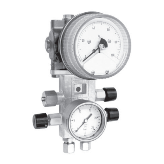
- Page 1 EB 9520 EN Translation of original instructions Media 05 with indicating unit and dp cell, with valve block and pressure gauge for operating pressure (right) Media 05 Differential Pressure and Flow Meter Edition November 2010...
- Page 2 Î For the safe and proper use of these instructions, read them carefully and keep them for later reference. Î If you have any questions about these instructions, contact SAMSON‘s After-sales Service Department (aftersalesservice@samson.de). The mounting and operating instructions for the devices are included in the scope of delivery.
-
Page 3: Table Of Contents
Contents Safety instructions and measures ..............4 Notes on possible property damage ..............7 Design and principle of operation ..............8 Technical data .....................10 Installation ....................12 Arrangement of instruments for liquid level measurement ........12 3.2 Arrangement of devices for flow rate measurement .........12 3.3 Media 05 indicating unit ................12 Differential pressure lines ................14 3.5 Orifice flange (orifice plate assembly) ............14 Accessories ....................16... -
Page 4: Safety Instructions And Measures
1 Safety instructions and measures Intended use The Media 05 Differential Pressure and Flow Meter is used to measure and indicate the dif- ferential pressure or derived measuring variables for gases and liquids. Typical application include liquid level measurement on pressure vessels, differential pressure measurement be- tween flow and return flow pipes, pressure drop measurement on valves and filters as well as flow rate measurement according to the differential pressure method. - Page 5 When returning devices for oxygen service for repair, the sender assumes full responsibility that the devices are handled to meet all requirements stipulated by VBG 62 or similar regula- tions until they are handed over to the manufacturer. Otherwise, SAMSON does not accept any responsibility. Reasonably foreseeable misuse The Media 05 Differential Pressure and Flow Meter is not suitable for the following applica-...
- Page 6 Safety instructions and measures Revisions and other modifications Revisions, conversions or other modifications of the product are not authorized by SAMSON. They are performed at the user's own risk and may lead to safety hazards, for example. Furthermore, the product may no longer meet the requirements for its intended use. Use of the device is no longer permitted.
-
Page 7: Notes On Possible Property Damage
Î Make sure that the dp cell and all SAMSON accessories only come into contact with gaseous oxygen. Î When returning devices for oxygen service for repair, the sender assumes full responsibility that the devices are handled to meet all requirements stipulated by VBG 62 or similar regulations until they are handed over to the manufacturer. -
Page 8: Design And Principle Of Operation
When the metal tag enters the inductive field of the associated proximity switch, it as- operation sumes a high resistance (contact open). The Media 05 Differential Pressure and Flow When the metal tag leaves the inductive Meter is used to measure and indicate the field, it assumes a low resistance (contact differential pressure or derived measuring closed). - Page 9 Design and principle of operation Differential pressure cell Housing of indicating unit dp cell Gear segment High-pressure chamber Pointer mechanism Dial plate Low-pressure chamber Range springs Limit contact (alarm contact) Measuring diaphragm Metal tag Diaphragm plates Proximity switches for alarm contacts A1 Diaphragm stem and A2 Lever...
-
Page 10: Technical Data
Design and principle of operation 2.1 Technical data Note All pressure in bar (gauge); all errors and deviations are specified in % of the adjusted mea- suring span. Media 05 Differential Pressure and Flow Meter Nominal range mbar 0 to 0 to 0 to 0 to 0 to... - Page 11 Design and principle of operation Degree of protection IP 54 according to VDE 0470-1/EN 60529 Weight, approx. 2.6 kg without valve block · 4.6 kg with valve block Materials Version Standard version Housing Brass (CW617N) or CrNi steel Measuring diaphragm and 2) seals Springs, diaphragm plates, CrNi steel functional parts, lever Housing of indicating unit Polycarbonate Based on upper measuring range value Other on request EB 9520 EN...
-
Page 12: Installation
Installation 3 Installation Note Special screw fittings are required to connect 3.1 Arrangement of the differential pressure lines. Depending on instruments for liquid level the device arrangement, seal any connec- tions left unused with stoppers or vent plugs measurement (see section 4.4). In arrangements as illustrated in the second schematic drawing, the additional height z is Carefully clean the connections before at-... - Page 13 Installation Liquid level measurement Illustration with SAMSON valve block Measuring range Measured height Additional height Compensation height – – – Measurements in cryogenic Measurement on pressure vessels Measurements on open vessels systems (liquefied gases) with condensing or non- with the meter located in a...
-
Page 14: Differential Pressure Lines
3.5 Orifice flange (orifice plate assembly) Î The direction of flow must correspond to the arrow on the orifice plate. Î Unobstructed pipe sections are required upstream and downstream of the orifice plate assembly. For the orifice tubes de- livered by SAMSON, these section are ensured by the weld-on calibration pipes. For orifice flanges, the unobstruct- ed pipe section upstream of the orifice plate is specified in the order confirma- tion. Î Make sure the orifice plate assembly as well as the gaskets are properly aligned with the pipeline. - Page 15 Installation Type 90 Orifice Flange Inlet 20 to 50 x d Outlet 5 x d Location of the differential pressure lines on the orifice plate assembly For gas For steam For liquids Fig. 3: Orifice flange (orifice plate assembly) EB 9520 EN...
-
Page 16: Accessories
It is attached directly to the bottom of the dp 4.4 Accessories for connection cell. When measuring the flow rate of liquids and The devices are delivered without screw fit- gases, the SAMSON valve block can also be tings (oxygen versions are protected against mounted upside down to ensure the assign- contamination by four NBR blanking plugs). ment of plus (+) to plus (+) and minus (–) to Required screw fittings, screw plugs or vent minus (–) remains unchanged. Due to this re-... - Page 17 Holes for lead-seal wires Shut-off valves Shut-off valves – Pressure gauge connection Connection for measuring lines Fig. 4: SAMSON valve block Flow rate measurement From the dp cell Shut-off valves Equalizing valve To the indicating unit Fig. 5: Shut-off and equalizing valves (separate or combined as a block)
-
Page 18: Start-Up
Start-up 5 Start-up 4. Wait a while. Open both vent screws of the dp cell one after the other until the escaping condensate is free of bubbles. NOTICE Retighten the screws. Vent the compensa- Risk of damage to the differential pressure tion chambers in the same way. -
Page 19: Operation
Operation 2. Close the equalizing valve or bypass of In case of larger deviations, remove the the valve block. pointer with an appropriate tool. Align the dial plate in the mid-position. Re- 3. Open the low-pressure line. mount the pointer on the axis in the zero 4. -
Page 20: Adjusting And Modifying The Measuring Range
− Max. oxygen pressure 30 bar 5. Pressurize measuring chamber again un- til the pointer indicates the end value. Make sure that the dp cell and all SAMSON accessories (e.g. valve block) only come into 6. Check the end value of the measuring contact with gaseous oxygen. - Page 21 Start-up Screws Recess for screwdriver Cover plate Fastening screw Measuring unit frame Dial screws Supply air reducing sta- tion with oil filter and test pressure gauge Test pressure Precision regulator with Class 0.1 pressure gauge Fig. 7: Test arrangement and changing the measuring range EB 9520 EN...
-
Page 22: Version With Limit Contacts
Version with limit contacts 7 Version with limit contacts One or two proximity switches can be installed as alarm contacts (A1 and A2) as follows: Contact and function Contact Image 52 41 42 made with Min – A1 as main contact Bottom – – Min – A1 as main contact Bottom Min – A2 as pre-alarm contact Min – A1 as main contact... - Page 23 Version with limit contacts Max. contact 3. Undo the clamping screw (Fig. 9) at the proximity switch bracket and manually Always adjust the switching points according move the contact into the desired switch- to the rising characteristic. The top edge of ing position (note that the middle of the the contact causes the contact to be made.
-
Page 24: Retrofitting Or Replacing The Contact Unit
Version with limit contacts 2. Slightly tighten the clamping screw. metal tags reach into the proximity switches without touching the contacts. 3. Check the switching point and readjust, if necessary. 5. Fasten the contact unit (2) to the measur- ing unit frame using two slotted head Adjustment without pressure specifications screws (5). - Page 25 Version with limit contacts Positioning notch Contact unit Measuring unit frame Connecting cable A1 Connecting cable A2 Slotted-head screws Phillips screw Cable gland Fig. 10: Retrofitting alarm contacts EB 9520 EN...
-
Page 26: Dimensions
Dimensions 8 Dimensions Ø110 Pressure gauge connection G ½-LH with coupling sleeve G ½ for pressure gauge NG 100 and 12x2 O-ring as well as for G ¼ for pressure gauge NG 63 with G ¼ seal EB 9520 EN... - Page 27 Dimensions Pipe mounting 129.5 Valve block when mounted upside down SW14, G ¼ EB 9520 EN...
- Page 28 Dimensions Drill pattern for wall/panel mounting Center of the indicator unit Two Ø 8.5 mm holes for fastening at the back of the dp cell (M8 screws) 17.5 Two Ø8.5 mm holes for fastening at the valve block (M8 screws) EB 9520 EN...
- Page 29 EB 9520 EN...
- Page 32 EB 9520 EN SAMSON AKTIENGESELLSCHAFT Weismüllerstraße 3 · 60314 Frankfurt am Main, Germany Phone: +49 69 4009-0 · Fax: +49 69 4009-1507 samson@samson.de · www.samson.de...
Need help?
Do you have a question about the Media 05 and is the answer not in the manual?
Questions and answers