Samson Media 6 Original Instructions Manual
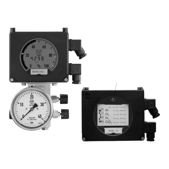
Differential pressure meter
Hide thumbs
Also See for Media 6:
- Mounting and operating instructions (34 pages) ,
- Mounting and operating manual (48 pages) ,
- Mounting and operating instructions (42 pages)

Related Manuals for Samson Media 6


Summary of Contents for Samson Media 6
- Page 1 Media 6 Differential Pressure Meter Configuration with TROVIS-VIEW 4 TROVIS-VIEW 4 Software for Media 6 Operating Instructions EB 9527-2 EN Firmware: TROVIS-VIEW 4/Media 6 V3.10-3.19 ® Edition February 2016 Electronics from SAMSON...
- Page 2 Definition of signal words DANGER! NOTICE Hazardous situations which, if not Property damage message or mal- avoided, will result in death or seri- function ous injury Note: WARNING! Additional information Hazardous situations which, if not avoided, could result in death or seri- Tip: ous injury Recommended action...
-
Page 3: Table Of Contents
Contents TROVIS-VIEW 4 software ................5 General ......................5 Communication with Media 6 Differential Pressure and Flow Meter ....6 User interface ....................7 Liquid level measurement ................7 3.1.1 Identification ....................8 3.1.2 General data ....................8 3.1.3 Tank ......................10 3.1.4 Medium ......................14 3.1.5 Maintenance ....................21 3.1.6 Certificates and approvals ................22 3.1.7 Operation ....................23 Flow measurement, counting flow rate measurement, differential pressure mea-... - Page 4 EB 9527-2 EN...
-
Page 5: Trovis-View 4 Software
Refer to the Operating Instructions u EB 6661 on how to use the TROVIS-VIEW 4 software. The TROVIS-VIEW 4 software allows users to configure and parameterize various smart SAMSON devices (in this case, the Media 6 Differential Pressure Meter) over a common user interface. It consists of the operator interface, communication server, and the device-specific module. -
Page 6: Communication With Media 6 Differential Pressure And Flow Meter
To download configuration data from the software to the SAMSON memory pen or to up- load data from the memory pen, a SAMSON modular adapter must be inserted into the seri- al interface of the PC or laptop to connect the memory pen. See the Operating Instructions u EB 6661 for TROVIS-VIEW 4 software. -
Page 7: User Interface
User interface 3 User interface Start TROVIS-VIEW 4 (Media 6). The interface appears with a menu bar and tool bar and the tree structure for Media 6, which includes all relevant parameters organized in folders and subfolders. You only perform the settings needed for communication with a Media 6 device. −... -
Page 8: Identification
User interface 3.1.1 Identification Data relevant for unique identification of the Media 6 device are shown. These details cannot be edited. [Identification] Type Media 6 Differential Pressure Meter (Type 5006) Version Firmware version Addition Identifier for different versions Serial no. Serial number of the connected Media 6 device 3.1.2 General data They allow the settings relevant for a measuring procedure to be made by selecting options... - Page 9 User interface 'Filling limit reached' signal Select either 'Overflow' or 'Operating filling limit'. Both values for these options are to be entered in [Medium] depending on the specified tanks. The bar graph blinks on the display when the adjusted limit is exceeded. 'Equalizing valve open' signal When 'Yes' is selected, a signal is activated when the equalizing valve on the valve block be- tween the (+) and (–) measuring lines (see u EB 9527-3, Fig. 4) is opened.
-
Page 10: Tank
User interface 3.1.3 Tank Certain data about the tank shape must be known to calculate tank characteristic. A default set of data with predetermined values is available in the tank database. Load these data and overwrite them with the corresponding tank geometry data and settings. [Tank] Enter the geometrical data required to calculate the tank and its characteristic. - Page 11 User interface [Identifier] A maximum of 15 characters can be entered to describe the type of tank or the tank ID. The text appears in upper-case letters. The tank ID runs across the display of the Media 6 device. [Tank database] [Load data You can load and modify existing tank geometrical data from the database.
- Page 12 User interface Static column [H] in m Max. possible liquid column. This corresponds to the inside length (horizontal tank) or inside height (upright tank). The value is automatically calculated. Total volume [V] in m³ Corresponds to the geometric tank volume (gross useable tank volume in m³). The value is automatically calculated, provided it has not been entered (existing data).
- Page 13 User interface EB 9527-2 EN...
-
Page 14: Medium
User interface 3.1.4 Medium [Medium] The data for a maximum of four media can be entered. EB 9527-2 EN... - Page 15 User interface [Medium 1] to [Medium 4] − Medium database − General medium data − Tank pressure − Density calculations − Densities − Operating filling limit, hazard warning − Calculated values [Medium database] [Load data You can load and modify existing media data from the database. EB 9527-2 EN...
- Page 16 Medium identifier A maximum of 8 characters can be entered to describe the tank content (stored medium). The text appears in upper-case letters on the display of the Media 6 device. Unit · Drop-down list with six entries − m³, %, kg, L, ft³, lbs Shrink factor Enter the shrink factor valid at the operating temperature of the tank.
- Page 17 User interface Medium data Enter the gas column correction as well as the liquid density and mixture density (see [Densi- ties]). Gas column correction · Yes/No Yes · The gas column correction increases the accuracy of the filling level indication. It can only be performed if the gas density in the tank and in the low-pressure pipe are known. Therefore, enter the density after activating the gas column correction (see [Density]).
- Page 18 User interface Liquid density in m³ Density of medium at 1 bar (abs) and boiling temperature. To improve the accuracy of the in- dicated filling level, enter the liquid density at operating conditions. In this case, the operat- ing pressure density must be entered and changed manually (see [Operating pressure]). This makes the filling level reading more precise.
- Page 19 User interface [Operating filling limit, hazard warning] − Operating filling limit Operating filling limit in % A blinking bar graph element on the display indicates when the operating filling limit has been reached. A marking can be fixed in the range between 0 % and 95 %. This is used to calculate the tank content.
- Page 20 User interface [Save ...] The data can be saved to a file (.txt), e.g. filling level_01.txt, and processed on a computer using other standard software. EB 9527-2 EN...
-
Page 21: Maintenance
User interface 3.1.5 Maintenance [Maintenance] − Error messages − Other maintenance data − Reset − Error history [Error messages] Information on error messages (e.g. error status, sum of error codes) are shown and can be reset. [Other maintenance data] Measuring range reading of the connected Media 6 device. [Reset] Restart the Media 6 device. -
Page 22: Certificates And Approvals
User interface 3.1.6 Certificates and approvals [Certificates and approvals] Status details of the connected Media 6 device Yes/No reading − Ex certification − Oxygen − Compatibility with paint Information on the connected Media 6 device concerning certificates and approvals. Ex certification Indicates whether the connected Media 6 device is approved for use in hazardous areas. Oxygen Indicates whether the connected Media 6 device is approved for oxygen service. -
Page 23: Operation
User interface 3.1.7 Operation [Operation] − Display − Status [Display] Depending on the operating mode selected, a list of all readings appears. − Identifier · Same as entered in [Tank] > [Identifier]. − Medium identifier · Same as entered in [General medium data] > [Medium identifier]. −... - Page 24 User interface [Status] Status details of the connected Media 6 device − Limit switch A1 · State of limit switch A1 (On/Off) − Limit switch A2 · State of limit switch A2 (On/Off) − Tap position · State of equalizing valve between the (+) and (–) measuring lines. Only vis- ible if the ['Equalizing valve open' signal] = 'Yes' (see section 3.1.2 on page 8).
-
Page 25: Flow Measurement, Counting Flow Rate Measurement, Differential Pressure Mea- Surement, Level Measurement In Transportation Vehicles
In the 'Specialist' user level, [Flow rate mode], [Counting flow rate mode], [Differential pres- sure mode], [Filling level in tank truck] can also be selected. The user level is password-protected: 'samson' for first installation (TROVIS-VIEW 4 3.20 and higher), 'DURCHFLUSS' after update (TROVIS-VIEW 4 before 3.20) More details in u EB 6661 for TROVIS-VIEW 4 software. -
Page 26: Flow Rate Measurement
User interface 3.2.1 Flow rate measurement [Identification] > [Operating mode] Select [Flow rate mode]. [Flow rate mode] In the [Flow rate] folder, enter the data required for flow rate measurement. [Flow rate] is visible together with its associated parameters: [Medium density] Density [Rho] in kg/m³... - Page 27 User interface [Low-flow cut-off] At low flow velocities, no reproducible measurements are possible in the lowest measuring range. As a result, low-flow cut-off is active in root-extracting flow mode. Low-flow cut-off acts on the current output and the display. Adjustable in 7 to 20 % range of Q = 100 %. The flow rate is not registered in the adjusted range as a result.
- Page 28 User interface The pressure range can be selected within the specified limits. The selected operating pres- sure must match the entered density at operating conditions. The operating pressure is shown as 'PTANK' on the display of the Media 6 device. The unit selected in this case relates to the previous 'Pressure' parameter. A drop-down list contains the units: mbar, bar, kPa, psi, mm/H O, cm/H O, m/H...
-
Page 29: Counting Flow Rate Measurement
User interface 3.2.2 Counting flow rate measurement [Identification] > [Operating mode] Select [Counting flow rate mode]. [Counting flow rate mode] In the [Counting flow rate mode] folder, enter the required data. [Counting flow rate mode] is visible together with its associated parameters: Besides the parameters entered in [Flow rate], additional data in [Flow rate specifications] and [Calculated values] are required: [Count]... - Page 30 User interface [Calculated values] − Max. flow rate − Max. no. of counts − Max. recordable counts [Max. flow rate] [MCN] in m³/h Reading of the maximum recordable flow rate (20 mA = 100 %). [Max. no. of counts] Max. 99 999 999 reading Maximum recordable number of counts.
-
Page 31: Differential Pressure Measurement
User interface 3.2.3 Differential pressure measurement [Identification] > [Operating mode] Select [Differential pressure mode]. [Differential pressure] In the [Differential pressure] folder, enter the required data. [Differential pressure] is visible together with its associated parameters: [Differential pressure specifications] − Min. differential pressure −... - Page 32 User interface [General medium data] − Medium identifier Medium identifier A maximum of 8 characters can be entered to describe the medium. The text appears in up- per-case letters. The medium identifier is shown on the display of the Media 6 device. [Pressure specifications] −...
-
Page 33: Level Measurement In Transportation Vehicles
User interface 3.2.4 Level measurement in transportation vehicles [Identification] > [Operating mode] Select the function [Filling level in tank truck]. [Filling level in tank truck] In the [Filling level in tank trunk] folder, enter the required data. See details in section 3.1 on page 7. -
Page 34: Settings At The Media 6 Device
After changing the range springs or diaphragm, the Media 6 device must be recalibrated. In this case, an update of TROVIS-VIEW 4 with the "Z-Adj.tro" file is required. Note: Basic calibration must only be performed after consulting SAMSON since special knowledge is required in this case. EB 9527-2 EN... -
Page 35: Data Exchange
To establish communication, the serial interface of the computer or notebook must be con- nected to the serial interface port of the Media 6 device using the SAMSON connecting ca- ble. TROVIS-VIEW 4 must be in the online mode. In this case, communication is established per- manently between the Media 6 device and TROVIS-VIEW. -
Page 36: Write Data From Trovis View 4 To The Media 6 Device
Data exchange To read the Media 6 device, click on in the toolbar. 4.2 Write data from TROVIS VIEW 4 to the Media 6 device Deactivate the write protection at the selector switch on the Media 6 device (front left on the housing). Set slider switch 4 to OFF (see write protection in u EB 9527-3). Menu bar [Device] [Write] To write data to the Media 6 device, click on... - Page 37 The maximum span adjustment is 1:5. The SAMSON memory pen can also be used to exchange data between TROVIS-VIEW 4 and the Media 6 device. The memory pen serves as a data carrier and is able to load and store data from the Media 6 device or TROVIS-VIEW 4 in its non-volatile memory.
- Page 38 EB 9527-2 EN...
- Page 39 EB 9527-2 EN...
- Page 40 SAMSON AG · MESS- UND REGELTECHNIK Weismüllerstraße 3 · 60314 Frankfurt am Main, Germany Phone: +49 69 4009-0 · Fax: +49 69 4009-1507 EB 9527-2 EN samson@samson.de · www.samson.de...
Need help?
Do you have a question about the Media 6 and is the answer not in the manual?
Questions and answers