
Related Manuals for Samson 024.85


Summary of Contents for Samson 024.85
- Page 1 Originalbetriebsanleitung Translation of the original operating instruction 024.85 / 024.86 / 024.87 Elektrische Stellungsanzeigen Electrical position indicators...
- Page 2 Original Betriebsanleitung Translation of the original operating instructions Elektrische Stellunganzeigen Typ 024.85/024.86/024.87 Electrical position indicators type 024.85/024.86/024.87 Printed in Germany Print-Date: 18.06.2021 Erstelldatum / Creation date 18.06.2021 Änderungsdatum / Date of change 18.06.2021 Version © 1994 - 2021 SED Flow Control...
-
Page 3: Table Of Contents
Original Betriebsanleitung Elektrische Stellunganzeigen Typ 024.85/024.86/024.87 Inhaltsverzeichnis: Einleitung ..............................1 1.1. Hinweise zur Betriebsanleitung ......................2 Sicherheit..............................3 2.1. Sicherheitshinweise ..........................3 2.2. Gefahrenklassifikation ......................... 3 2.3. Bestimmungsgemäße Verwendung..................... 4 2.4. Missbrauch ............................4 2.5. Allgemeine Sicherheitsbestimmungen ....................4 2.6. - Page 4 Original Betriebsanleitung Elektrische Stellunganzeigen Typ 024.85/024.86/024.87 5.3.1. Montage des Anbausatzes ......................19 5.3.2. Montage der elektrischen Stellungsanzeige ................20 5.3.3. Einstellung der Schaltpositionen ....................20 5.3.4. Elektrischer Anschluss ....................... 21 5.3.5. Abschluss der Montage......................21 5.3.6. Demontage ..........................21 5.4.
- Page 5 Original Betriebsanleitung Elektrische Stellunganzeigen Typ 024.85/024.86/024.87 Table of contents Introduction..............................28 1.1. Information about the operating instructions................... 29 Safety ................................30 2.1. Safety Information ..........................30 2.2. Hazard classification .......................... 30 2.3. Intended use ............................31 2.4. Misuse ............................... 31 2.5.
- Page 6 Original Betriebsanleitung Elektrische Stellunganzeigen Typ 024.85/024.86/024.87 5.3.2. Assembly of the electrical position indicator ................47 5.3.3. Adjustment of the switching position ..................47 5.3.4. Electrical installation ......................... 48 5.3.5. Finalization of the installation ....................48 5.3.6. Disassembly ..........................48 5.4.
-
Page 7: Einleitung
Original Betriebsanleitung Elektrische Stellunganzeigen Typ 024.85/024.86/024.87 1. Einleitung Wenn Sie Fragen zum Gerät haben, wenden Sie sich bitte unter Angabe der Seriennummer an den Kundenservice von: SED Flow Control GmbH Am Schafbaum 2 D-74906 Bad Rappenau Postfach 1306 D-74900 Bad Rappenau... -
Page 8: Hinweise Zur Betriebsanleitung
Original Betriebsanleitung Elektrische Stellunganzeigen Typ 024.85/024.86/024.87 1.1. Hinweise zur Betriebsanleitung Sicheres Betreiben Die Betriebsanleitung enthält wichtige Hinweise, das Gerät sicher und sachgerecht zu installieren. Ihre Beachtung hilft, Gefahren zu vermeiden, Reparaturkosten und Ausfallzeiten zu vermindern und die Zuverlässigkeit und die Lebensdauer des Geräts zu erhöhen. -
Page 9: Sicherheit
Original Betriebsanleitung Elektrische Stellunganzeigen Typ 024.85/024.86/024.87 Sicherheit 2.1. Sicherheitshinweise Warnung Die Betriebsanleitung enthält wichtige Informationen zur Sicherheit! Das Nichtbeachten dieser Hinweise kann zu gefährlichen Situationen führen. Die Betriebsanleitung muss gelesen und verstanden werden! 2.2. Gefahrenklassifikation Gefahr Warnt vor einer unmittelbaren Gefahr! -
Page 10: Bestimmungsgemäße Verwendung
Bestimmungsgemäße Verwendung Die elektrische Stellungsanzeigen werden ausschließlich zur elektrischen und optischen Endlagenerfassung eines Ventils eingesetzt. Zur Rückmeldung der Stellungen „offen“ und „geschlossen“ sind bei Typ 024.85 zwei mechanisch arbeitende Subminiatur-Schalter integriert. Bei Typ 024.86 werden Namur-Sensoren und bei 024.87 3 Draht PNP-Sensoren verbaut. Die Positionsanzeigen sind so ausgeführt, dass sie auf alle fremdgesteuerten Armaturen mit den Membranabmessungen MA25 –... -
Page 11: Restrisiken
Original Betriebsanleitung Elektrische Stellunganzeigen Typ 024.85/024.86/024.87 Regeln zur Unfallverhütung Neben der Betriebsanleitung und den im Verwenderland und an der Einsatzstelle geltenden verbindlichen Regelungen zur Unfallverhütung sind auch die anerkannten fachtechnischen Regeln für sicherheits- und fachgerechtes Arbeiten zu beachten. Vor Beginn der Arbeit Informieren Sie sich vor Beginn der Arbeiten über Erste Hilfe- und Rettungsmöglichkeiten (Notarzt, Feuerwehr,... -
Page 12: Verantwortliche Personen Bestimmen
Original Betriebsanleitung Elektrische Stellunganzeigen Typ 024.85/024.86/024.87 2.7.1. Verantwortliche Personen bestimmen ▪ Nur sicherheitstechnisch unterwiesenes Personal einsetzen. ▪ Zuständigkeiten des Personals für Installation, Inbetriebnahme und Instandsetzung klar festlegen. ▪ Regelmäßig das sicherheits- und gefahrenbewusste Arbeiten des Personals unter Beachtung der Betriebsanleitung kontrollieren. -
Page 13: Transport / Lagerung / Entsorgung
Hinweis Ein passender Montagesatz wird benötigt, um die Funktionalität zu gewährleisten. Dieser ist jedoch nicht im Lieferumfang der Stellungsanzeigen 024.85/024.86/024.87 enthalten. Sollten Sie ein Ventil als Kompletteinheit mit der elektrischen Stellungsanzeige, Montagesatz und Zubehör bestellt haben, so ist dieses bereits vormontiert und werkseitig voreingestellt. Eine Überprüfung der Funktion im eingebauten Zustand ist dennoch vorzunehmen. -
Page 14: Lagerung
Original Betriebsanleitung Elektrische Stellunganzeigen Typ 024.85/024.86/024.87 3.3. Lagerung Hinweis Bei Nichtbeachtung kann das Gerät beschädigt werden! Gefahr Verletzungsgefahr nach Wiedereinbau! Prüfen Sie das Gerät auf etwaige Beschädigungen und auf eine korrekt durchgeführte Montage, insbesondere auf gelockerte Montageschrauben Um ein nicht genutztes Gerät auch über einen längeren Zeitraum funktionsfähig zu halten, müssen einige Punkte beachtet werden: ▪... -
Page 15: Technische Daten
Original Betriebsanleitung Elektrische Stellunganzeigen Typ 024.85/024.86/024.87 Technische Daten 4.1. Allgemeine technische Daten 024.85 024.86 024.87 Bild (Inklusive Montagesatz) Adapter 1.4305 Spindel 1.4301 Material Montagesatz O-Ring Nocken 1.4305 Sensor-/Schalterspezifisch Induktivschalter (Öffner) Induktivschalter Schaltertyp Mikroschalter Namur (Schließer) PNP Ausgangsart 2-Draht 3-Draht 24 V DC (10 … 30 V DC) - Page 16 Original Betriebsanleitung Elektrische Stellunganzeigen Typ 024.85/024.86/024.87 024.85 024.86 024.87 Gesamtsystem Haube PC (Markolon) Gehäuse- material Unterteil PP + 30% GF O-Ring Dichtscheibe Dichtungs- Dichtung material Verschluss- schraube Maximaler Hub Ventilspindel 75 mm Schutzart Stellungsanzeigen IP 65 (EN 60529) -10°C … +50°C Umgebungstemperatur Voll integriert PG 13,5 BOPLA DZP 13 (Bopla Gehäuse Systeme GmbH...
-
Page 17: Betriebstemperaturen
Niederspannungsrichtlinie 2014/35/EU ▪ EMV-Richtlinie 2014/30/EU Für den Einsatz in explosionsgefährdeten Bereichen ist für 024.86 eine ATEX Version nach Richtlinie 2014/34/EU verfügbar. 4.4. Maße Die Abmaße sind für folgende Typen identisch: 024.85/024.86/024.87 © 1994 - 2021 SED Flow Control BA210008 Version: a... -
Page 18: Typenschild
Original Betriebsanleitung Elektrische Stellunganzeigen Typ 024.85/024.86/024.87 Hinweis Die Abmessungen der optionalen Ausführungen können abweichen! Typenschild © 1994 - 2021 SED Flow Control BA210008 Version: a... -
Page 19: Installation
Original Betriebsanleitung Elektrische Stellunganzeigen Typ 024.85/024.86/024.87 Das Typenschild wird in Form eines Klebeschilds auf dem Gerät angebracht und enthält wichtige Informationen zum Betrieb. Eine detaillierte Aufschlüsselung des Matchcodes können Sie online unter www.sed.samsongroup.com unserem Produktkonfigurator ermitteln. Installation Gefahr Gefahr durch elektrische Spannung! -
Page 20: Aufbau
Original Betriebsanleitung Elektrische Stellunganzeigen Typ 024.85/024.86/024.87 5.2. Aufbau Abbildung 1 Explosionsdarstellung von Gehäuse und Haube Pos.-Nr. Benennung Menge Gehäuse Schutzhaube Unterlegscheibe PA 5,3x10 DIN 125 Flachkopfschrauben mit Schlitz M5x12 DIN EN ISO 1580 (DIN 85) © 1994 - 2021 SED Flow Control... - Page 21 Original Betriebsanleitung Elektrische Stellunganzeigen Typ 024.85/024.86/024.87 Abbildung 2 Explosionsdarstellung 024.85 Detail Pos.-Nr. Benennung Menge Gehäuse Vierkantmutter M4 Gewindestift M4x10 DIN 914 Haltewinkel Senkkopfschraube M3x60 DIN 965 Schieber Senkkopfschraube 4,8x19 DIN7982 Klemmleiste 6 x2,5 mm² Sicherungsring 2,3 DIN6799 Druckschraube DZP 13 Klemmkäfig KK 13...
- Page 22 Original Betriebsanleitung Elektrische Stellunganzeigen Typ 024.85/024.86/024.87 Abbildung 3 Explosionsdarstellung 024.86/024.87 Detail Pos.-Nr. Benennung Menge Gehäuse Vierkantmutter M4 Gewindestift M4x10 DIN 914 Haltewinkel Senkkopfschraube M3x60 DIN 965 Schieber Senkkopfschraube 4,8x19 DIN7982 Klemmleiste 6x2,5 mm² Sicherungsring 2,3 DIN6799 Druckschraube DZP 13 Klemmkäfig KK 13...
-
Page 23: Funktionsbeschreibung
Elektrische Stellunganzeigen Typ 024.85/024.86/024.87 5.2.1. Funktionsbeschreibung Die Stellungsanzeigen 024.85/024.86/024.87 ermöglichen eine einwandfreie Kontrolle und Anzeige der Schließ- und Öffnungsposition des Ventils. Die Signale werden bei Typ 024.85 durch zwei mechanische Mikroschalter realisiert, wohingegen die Typen 024.86/024.87 zwei Näherungsschalter nutzen. 5.2.2. Anschlussplan Kundenanschlüsse... -
Page 24: Montage & Demontage Der Stellungsanzeige
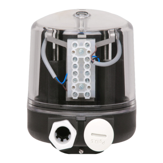
Original Betriebsanleitung Elektrische Stellunganzeigen Typ 024.85/024.86/024.87 Kundenanschlüsse Abbildung 6 Anschlussplan 024.87 5.3. Montage & Demontage der Stellungsanzeige Gefahr Prüfen sie das Gerät vor Inbetriebnahme auf korrekte Montage! Vergleichen Sie das Typenschild mit Ihrer Bestellung. Eine korrekte Montage und Funktion können nur gewährleistet, werden wenn die Steuereinheit zu der Armatur passt. -
Page 25: Montage Des Anbausatzes
Original Betriebsanleitung Elektrische Stellunganzeigen Typ 024.85/024.86/024.87 5.3.1. Montage des Anbausatzes → Antrieb Drucklos schalten. → Abdeckkappe von Antrieb oder bestehendes Zubehör (gemäß entsprechender Betriebsanleitung) demontieren. → Den Antrieb zunächst in „offen“-Stellung bringen. → Spindel des Ventils (ggf. über Kupplung) mit Spindel des Montagesatzes verbinden und handfest anziehen. -
Page 26: Montage Der Elektrischen Stellungsanzeige
Abbildung 1). → Führen Sie das Gehäuse (Pos. 1 Abbildung 8) vorsichtig über die Spindel bzw. Nocke (Pos. 2 bzw. 3 Abbildung 8). Achten Sie bei Typ 024.85 darauf den unteren Taster des Mikroschalters nicht zu verbiegen. Es empfiehlt sich diesen während des Durchführens von Hand zu... -
Page 27: Elektrischer Anschluss
Original Betriebsanleitung Elektrische Stellunganzeigen Typ 024.85/024.86/024.87 5.3.4. Elektrischer Anschluss → Verlegen Sie die Kabel durch die Kabelverschraubung und schließen diese entsprechend dem Schaltplan in Abschnitt 5.2.2 an die Klemmleiste an. Ziehen sie die Schauben der einzelnen Klemmstellen nach Herstellerangabe an. -
Page 28: Einbau Und Inbetriebnahme
Original Betriebsanleitung Elektrische Stellunganzeigen Typ 024.85/024.86/024.87 nicht der Fall, wird ein Ersatzteil benötigt. Defekte Teile nur durch originale Ersatzteile von SED Flow Control ersetzen. Kontaktieren Sie hierzu bitte Ihren zuständigen SED Vertriebspartner. 5.4. Einbau und Inbetriebnahme Hinweis Beachten Sie die in Ihrem Land gültigen Gesetze, Normen und Regelwerk zur konformen Verwendung der Steuereinheit! Stellen Sie vor dem Einbau sicher, dass die Steuereinheit für die Betriebsbedingungen geeignet ist. -
Page 29: Wartung Und Reinigung
Original Betriebsanleitung Elektrische Stellunganzeigen Typ 024.85/024.86/024.87 Wartung und Reinigung Wartungsarbeiten dürfen nur von geschultem Personal durchgeführt werden! Die Steuereinheit ist grundsätzlich wartungsfrei. Sie müssen in regelmäßigen Abständen geprüft werden. Die Abstände der Prüfungen müssen entsprechend der Einsatzbelastungen und der geltenden Regelwerke festgelegt und durchgeführt werden. -
Page 30: Herstellererklärung
Original Betriebsanleitung Elektrische Stellunganzeigen Typ 024.85/024.86/024.87 Herstellererklärung: 9.1. Niederspannungsrichtlinie 2014/34/EU © 1994 - 2021 SED Flow Control BA210008 Version: a... - Page 31 Original Betriebsanleitung Elektrische Stellunganzeigen Typ 024.85/024.86/024.87 © 1994 - 2021 SED Flow Control BA210008 Version: a...
-
Page 32: Richtlinie 2014/30/Eu (Emv)
Original Betriebsanleitung Elektrische Stellunganzeigen Typ 024.85/024.86/024.87 9.2. Richtlinie 2014/30/EU (EMV) © 1994 - 2021 SED Flow Control BA210008 Version: a... - Page 33 Original Betriebsanleitung Elektrische Stellunganzeigen Typ 024.85/024.86/024.87 © 1994 - 2021 SED Flow Control BA210008 Version: a...
-
Page 34: Introduction
Translation of the original operating instructions Electrical position indicators type 024.85/024.86/024.87 Introduction In case you have any queries about the device, please contact our customer services stating the serial number: SED Flow Control GmbH Am Schafbaum 2 D-74906 Bad Rappenau... -
Page 35: Information About The Operating Instructions
Translation of the original operating instructions Electrical position indicators type 024.85/024.86/024.87 1.1. Information about the operating instructions Safe operation The operating instructions contain important information for safe and correct installation of the device. Compliance with that helps preventing hazards, avoiding repair costs and downtime, and increasing reliability and operating life of the device. -
Page 36: Safety
Translation of the original operating instructions Electrical position indicators type 024.85/024.86/024.87 Safety 2.1. Safety Information Warning The operating instructions contain important safety information! Non-compliance with such information may cause hazardous situations. The operating instructions must be read and understood. 2.2. -
Page 37: Intended Use
The electrical position indicators are used exclusively for the electrical and optical end position detection of a valve. Two mechanically operating subminiature switches are integrated for type 024.85 to feedback the positions "open" and "closed". Type 024.86 uses 2 wire Namur sensors whereas 024.87 uses 3 wire PNP sensors. -
Page 38: Residual Risks
Translation of the original operating instructions Electrical position indicators type 024.85/024.86/024.87 Accident prevention rules In addition to the operating instructions and the binding rules and regulations for accident prevention applicable in the country of use and the place of operation, the approved technical rules for safe and professional working must be observed. -
Page 39: Appointment And Instruction Of Responsible Persons
Translation of the original operating instructions Electrical position indicators type 024.85/024.86/024.87 2.7.1. Appointment and instruction of responsible persons ▪ Only employ staff who has received safety instructions. ▪ Responsibilities and competencies of staff with regard to installation, programming and maintenance must be clearly defined. -
Page 40: Transport / Storage / Disposal
A suitable mounting kit is required to ensure the functionality. However, the kit is not included in the scope of delivery for the position indicators 024.85/024.86/024.87. If you have ordered a valve as a complete unit including an electrical position indicator, assembly set and accessories, the unit is already pre-assembled and pre-set at the factory. -
Page 41: Storage
Translation of the original operating instructions Electrical position indicators type 024.85/024.86/024.87 3.3. Storage Notice Bei Nichtbeachtung kann das Gerät beschädigt werden! Danger Danger of injury after reassembly! Please check, if there are any damages and ensure, that the mounting is correct, especially loosened erection... -
Page 42: Technical Data
Translation of the original operating instructions Electrical position indicators type 024.85/024.86/024.87 Technical Data 4.1. General technical data Type 024.85 024.86 024.87 Picture (including assembly set) Adapter 1.4305 Spindle 1.4301 Material assembly set O-ring 1.4305 Sensor/switch specific Inductive switch (N/O) Inductive switch (N/C) - Page 43 Translation of the original operating instructions Electrical position indicators type 024.85/024.86/024.87 Type 024.85 024.86 024.87 Overall system Cover PC (Markolon) Housing material Lower part PP + 30% GF O-ring Sealing Sealing washer material Sealing locking screw Maximum stroke of valve...
-
Page 44: Operating Temperatures
EMC Directive 2014/30/EU An ATEX version in accordance with Directive 2014/34/EC is available for use in hazardous areas for type 024.86. 4.4. Dimensions The dimensions are identical for the following types: 024.85/024.86/024.87 © 1994 - 2021 SED Flow Control BA210008 Version: a... -
Page 45: Type Plate
Translation of the original operating instructions Electrical position indicators type 024.85/024.86/024.87 Notice The dimensions of the optional versions may vary! 4.5. Type plate © 1994 - 2021 SED Flow Control BA210008 Version: a... -
Page 46: Installation
Translation of the original operating instructions Electrical position indicators type 024.85/024.86/024.87 The type plate is affixed to the device with an adhesive plate which contains important information about operation. A detailed breakdown of the match code can be found online at www.sed.samsongroup.com with our product configurator. -
Page 47: Structure
Translation of the original operating instructions Electrical position indicators type 024.85/024.86/024.87 5.2. Structure Figure 1 Exploded view of cover and lower part Pos.-No. Description Qty. Lower part Cover Washer PA 5,3x10 DIN 125 Flat head screw M5x12 DIN EN ISO 1580 (DIN 85) ©... - Page 48 Translation of the original operating instructions Electrical position indicators type 024.85/024.86/024.87 Figure 2 Exploded view of 024.85 Pos.-No. Description Qty. Lower part Square nut M4 Set screw M4x10 DIN 914 Bracket Countersunk bolt M3x60 DIN 965 Slider Countersunk bolt 4,8x19 DIN7982 Terminal 6 x2,5 mm²...
- Page 49 Translation of the original operating instructions Electrical position indicators type 024.85/024.86/024.87 Figure 3 Exploded view of 024.86/024.87 Pos.-No. Description Qty. Lower part Square nut M4 Set screw M4x10 DIN 914 Bracket Countersunk bolt M3x60 DIN 965 Slider Countersunk bolt 4,8x19 DIN7982 Terminal 6 x2,5 mm²...
-
Page 50: Functional Description
5.2.1. Functional description The position indicator 024.85/024.86/024.87 allows a flawless control and display of the closing and opening position of the valve. With type 024.85 the signals are realized by two mechanical microswitches, whereas types 024.86/024.87 use two proximity switches. -
Page 51: Assembly & Disassembly Of The Electrical Position Indicator
Translation of the original operating instructions Electrical position indicators type 024.85/024.86/024.87 customer ports Figure 6 Wiring diagram for 024.87 5.3. Assembly & disassembly of the electrical position indicator Danger Check the device for correct installation before initial operation! Compare the type plate with your order. Proper assembly and function can only be guaranteed if the control... -
Page 52: Installation Of Assembly Set
Translation of the original operating instructions Electrical position indicators type 024.85/024.86/024.87 5.3.1. Installation of assembly set → Switch the drive without pressure. → Demount cover cap of actuator or installed accessories (according to respective manual). → Put the drive in "open" position. -
Page 53: Assembly Of The Electrical Position Indicator
→ Carefully pull the lower part (pos. 1 in Figure 8 over the spindle or cam (pos. 2 or 3 in Figure 8). For type 024.85, be careful not to bend the lower lever of the microswitch. It is recommended to press it manually down during the installation. -
Page 54: Electrical Installation
Translation of the original operating instructions Electrical position indicators type 024.85/024.86/024.87 5.3.4. Electrical installation → Route the cables through the cable gland and connect them to the terminal according to the wiring diagram in section 5.2.2. Tighten the screws of the individual clamping points according to the manufacturer's specification. -
Page 55: Installation & Implementation
Translation of the original operating instructions Electrical position indicators type 024.85/024.86/024.87 5.4. Installation & implementation Notice Observe the laws, standards and regulations in force in your country for the compliant use of the control unit! Before installation, make sure that the control unit is suitable for operating conditions. This applies in particular to the function, materials, operating voltage and operating temperature. -
Page 56: Maintenance & Cleaning
Translation of the original operating instructions Electrical position indicators type 024.85/024.86/024.87 Maintenance & cleaning Maintenance is only allowed to be carried out by trained staff. Diaphragm valves are low-maintenance parts. They have to be checked and maintained periodically. These periods are depending on working load and have to be defined according to valid rules. -
Page 57: Manufacture´s Declaration
Translation of the original operating instructions Electrical position indicators type 024.85/024.86/024.87 Manufacture´s Declaration: 9.1. Low Voltage Dircetive 2014/34/EU © 1994 - 2021 SED Flow Control BA210008 Version: a... - Page 58 Translation of the original operating instructions Electrical position indicators type 024.85/024.86/024.87 © 1994 - 2021 SED Flow Control BA210008 Version: a...
-
Page 59: Directive 2014/30/Eu (Emc)
Translation of the original operating instructions Electrical position indicators type 024.85/024.86/024.87 9.2. Directive 2014/30/EU (EMC) © 1994 - 2021 SED Flow Control BA210008 Version: a... - Page 60 Translation of the original operating instructions Electrical position indicators type 024.85/024.86/024.87 © 1994 - 2021 SED Flow Control BA210008 Version: a...
- Page 61 – Americas 200 – SAMSON Turkey, Istanbul established 1984 – Frankfurt am Main, Germany 2,000 Total plot and production area: 11,053 m² – SAMSON USA, Baytown, TX, established 1992 MARKETS Total plot and production area: 9,200 m² – Chemicals and petrochemicals –...
Need help?
Do you have a question about the 024.85 and is the answer not in the manual?
Questions and answers