
Related Manuals for Samson Media 6 Z


Summary of Contents for Samson Media 6 Z
- Page 1 EB 9527-3 EN Translation of original instructions Media 6 with mounted valve block Differential Pressure Meters Media 6 · Media 6 Z Firmware version 3.12 Edition October 2015...
- Page 2 Î For the safe and proper use of these instructions, read them carefully and keep them for later reference. Î If you have any questions about these instructions, contact SAMSON‘s After-sales Service Department (aftersalesservice@samson.de). The mounting and operating instructions for the devices are included in the scope of delivery.
-
Page 3: Table Of Contents
Contents Safety instructions ..................5 Firmware version ..................6 Design and principle of operation ..............8 Technical data .....................10 Installation ....................12 Arrangement of devices for flow rate measurement .........12 Media 6 indicating unit ................12 Differential pressure lines ................14 Orifice flange (orifice plate assembly) ............14 4.4.1 Accessories ....................15 4.4.2... - Page 4 Contents Switching the LCD on and off ................28 Ammeter function ..................29 Battery operation ..................29 Memory pen communication ................30 Data transmission using a memory pen ............30 Communication with computer ..............32 Troubleshooting...................33 Servicing explosion-protected devices ............35 11.1 Firmware update..................35 11.2 Maintenance, calibration and work on equipment ..........36 Dimensions ....................37 EB 9527-3 EN...
-
Page 5: Safety Instructions
The replacement of printed circuit boards in explosion-protected devices is not permis- sible. NOTICE Oxygen service When the device is used for oxygen service, make sure that the dp cell and any SAMSON accessories (e.g. valve block) only come into contact with gaseous oxygen. EB 9527-3 EN... -
Page 6: Firmware Version
Firmware version 2 Firmware version Table 1: Firmware versions Firmware revisions A 2.03/B 2.03 A 2.10/B 2.10 Limit contacts The limit contacts A1 and A2 are configured using software to function as either min. or max. alarms. They can be con- figured separately using the keys on the device. - Page 7 Firmware version Firmware revisions V3.10 3.11 Battery operation Error remedied on changing to power-saving mode. Small corrections made. V3.11 V3.12 Error detection Detection and treatment of error codes 1 and 32768 changed. EB 9527-3 EN...
-
Page 8: Design And Principle Of Operation
(1.4) out of the pressure chamber Operating mode: liquid level measurement Counting pulse (Media 6 Z) and converted into an electric signal by the travel sensor (2). EB 9527-3 EN... - Page 9 Design and principle of operation Indicating unit with LCD Connector A = 12 to 36 V DC = 4 to 20 mA Min./max. alarm A1 Connector B Min./max. alarm A2 or pulse output (Media 6 Z) Serial interface μP FRAM Differential pressure cell 1.1 Measuring diaphragm 1.2 Range spring 1.3 Lever 1.4 Flexible disk dp cell...
-
Page 10: Technical Data
Design and principle of operation 3.1 Technical data Table 2: Technical data All pressure in bar (gauge) · All errors and deviations are specified in % of the adjusted measuring span Media 6 Differential Pressure Meter 0 to 0 to 0 to 0 to 0 to 0 to 0 to... - Page 11 Design and principle of operation Permissible ambient temperature T6: –20 to +60 °C –40 to +70 °C range T5: –20 to +70 °C Perm. storage temperature range –40 to +80 °C Use of Media 6 with gaseous Max. temperature: +60 °C oxygen Max. oxygen pressure: 30 bar Degree of protection according to IP 65 EN 60529...
-
Page 12: Installation
When returning devices for oxygen service for repair, the sender assumes full responsibility that the devices are handled to meet all requirements stipulated by VBG 62 or similar regulations until they are handed over to the manufacturer. Otherwise, SAMSON AG does not accept any responsibility. - Page 13 Separation chamber Installation Standard Reverse Standard Standard Reverse SAMSON valve blocks can be mounted upside down to ensure the assignment of plus (+) to plus (+) and minus (–) to minus (–) remains unchanged. Fig. 2: Arrangement of devices EB 9527-3 EN...
-
Page 14: Differential Pressure Lines
4.3 Differential pressure lines stream of the orifice plate assembly. For the orifice tubes delivered by SAMSON, these Install the differential pressure lines (pipes section are ensured by the weld-on calibra- with 12 mm outside diameter) as shown in tion pipes. -
Page 15: Accessories
The operating When measuring the flow rate of liquids and state must match the conditions calculated gases, the SAMSON valve block can also be during sizing as closely as possible. It is, mounted upside down. As a result, the as- however, favorable to install equipment that signment of plus (+) to plus (+) and minus (–) -
Page 16: Shut-Off And Equalizing Valves
Installation 4.4.3 Shut-off and equalizing valves As an alternative to the SAMSON valve block, the two shut-off valves as well as the bypass valve/equalizing valve can also be installed as illustrated in Fig. 5. 4.4.4 Compensation chambers Compensation chambers that establish a constant liquid column are required when measuring steam. -
Page 17: Electrical Connection
(TEST). The serial interface is not approved for use in hazardous areas. As a result, only the intrinsi- cally safe SAMSON memory pen must be connected to transfer data. NOTICE Selection of cables and wires · Observe section 12 in EN 60079‑14 (VDE 0165) when run- ning several intrinsically safe circuits in one multi-core cable. -
Page 18: Device Connector
Electrical connection 5.1 Device connector Connector B · Limit contacts/pulse output Connection of two software limit contacts in Connector A · Power supply type of protection Ex ia IIC for control circuits The same pair of conductors transmit the 4 according to NAMUR on switching amplifier to 20 mA measuring signal and the required according to EN 60947-5-6 power supply (U... -
Page 19: Operation
Operation GEFAHR WARNING − Degree of protection IP 65 is no longer valid when the cable socket is removed from the device connector. − Protect the device connector against moisture during installation and transport by keeping the cable socket part screwed on and sealed. Table 4: Overview of functions of both software limit contacts A1 and A2 at connector B Proximity switch 1 min./1 max. -
Page 20: Switching Over To Display Mode
Operation Further details on the display and operating controls can be found at the back of these in- structions. 6.1.1 Switching over to display mode Depending on the operating mode, each pressing of the key allows you to switch between the default display and up to eight other display readings. - Page 21 Operation Table 5: Operating mode Counting flow Liquid level Flow rate mea- Differential pressure Operating mode rate measure- measurement surement measurement ment Default mode Default Displayed readings Filling level Flow rate Meter reading Differential pressure values ΔP ΔP FLOW ΔP0 MCN (/R) MCN (/R) ∆P ∆P100...
-
Page 22: Start-Up
Start-up 7 Start-up 7.1 Liquid level measurement 1. Slowly open the low-pressure line. See Fig. 2, Fig. 3 and Fig. 4. 2. Close the equalizing valve or bypass of Based on the following valve positions on the the valve block. valve block upon delivery: 3. -
Page 23: Water Drainage
Start-up 7.3 Water drainage NOTICE When measuring gas, drain condensed wa- When using reverse installation (with the de- ter from the separation chambers from time vice mounted above the measuring point), to time. the differential pressure lines may partly get drained when depressurizing the system. -
Page 24: Settings
Settings 8 Settings 8.2 Selecting the gas type Select the required gas type over the posi- 8.1 Write protection tions of switches 1 and 2 (see Fig. 7). The device has two write-protection func- Table 6: Selecting the gas type tions: Gas 1 1 OFF 2 OFF WRITE PROTECTION to prevent the operat-... -
Page 25: Checking Zero
Settings 8.3 Checking zero Press and hold key until ZERO and X, 0X mbar are displayed. Current signal I To check zero, make sure that the pressures indicates the current value in mA. in both measuring chambers are identical at ... -
Page 26: Checking The Measuring Range (Span)
Settings Activate write protection by setting switch 4 Note to ON. To calibrate the currently used gas, its read- Place the valve block or equalizing valve ing must be at least 85 % of the adjusted up- back into the operating position: per measuring range value ∆p100. - Page 27 The test medium must free of oil and grease when the device is used to measure oxygen. Process medium: gaseous oxygen · Max. temperature: +60 °C, max. oxygen pressure: 30 bar When the device is used for oxygen service, make sure that the dp cell and any SAMSON accessories only come into contact with gaseous oxygen.
-
Page 28: Adjusting Limit Contacts
Settings 8.5 Adjusting limit contacts Both limit contacts are preset by the software to function as either min. or max. contacts. 8.5.1 Max. filling limit during A1MIN or A1MAX as well as A2MIN or operation A2MAX appear on the display. Both con- tacts must be set and confirmed separately. -
Page 29: Ammeter Function
Settings 8.7 Ammeter function 8.8 Battery operation The SAMSON battery supply unit (order no. Note 1400-9744, not approved for hazardous ar- The ammeter function is not available during eas) can be connected to connector A for battery operation. supply over batteries. -
Page 30: Memory Pen Communication
Such records or configurations do not need to be loaded to TROVIS‑VIEW for conversion any longer. 9 Memory pen communication NOTICE In hazardous areas, only the intrinsically safe SAMSON memory pen must be con- nected to the serial interface for data ex- change. EB 9527-3 EN... - Page 31 Memory pen communication Table 7: Memory pen status Memory pen status Display Process MEMWR Write data from Media 6 to the memory pen Write and read MEMRD read Media 6 data from the memory pen MEMRD Read only Read Media 6 data from the memory pen Write only MEMWR Write data from Media 6 to the memory pen...
-
Page 32: Communication With Computer
Memory pen communication 9.2 Communication with com- puter The Media 6 can also be operated using a computer connected to the serial interface and the TROVIS-VIEW software. Refer to Operating Instructions u EB 9527-2 for more details on operation. NOTICE The serial interface is not approved for use in hazardous areas. -
Page 33: Troubleshooting
Troubleshooting 10 Troubleshooting All device errors (class E1 to E3) are logged in an error history, which can be read in Errors on the LCD are indicated by ERROR at TROVIS-VIEW (V3.11 and higher). the top of the display and the associated er- The errors are not saved. - Page 34 Troubleshooting using memory pen Contact the After-sales Service department If a SAMSON memory pen is available, it for more information (u aftersalesservice@ can be used to transfer new data to the de- samson.de). vice while the error is suppressed (approx.
-
Page 35: Servicing Explosion-Protected Devices
When updates are performed by a service viced, it must not be put back into operation employee appointed by SAMSON, the up- until a qualified inspector has assessed it ac- date is confirmed on the positioner by the cording to explosion protection require- test mark assigned by SAMSON’s Quality... -
Page 36: Maintenance, Calibration And Work On Equipment
– +, see Fig. 10). The serial interface (Fig. 10) is not approved for use in hazardous areas. As a result, only the intrinsically safe SAMSON memory pen must be connected to transfer data or proceed as described in section 11.1. 11.2 Maintenance, calibration... -
Page 37: Dimensions
Dimensions 12 Dimensions 141.5 Pressure sensor, depending on 180.5 manufacturer 32.5 Control panel 25.5 Pressure gauge, depend- ing on manufacturer Pressure gauge connections For NG 100 pressure gauge: Male thread G ½ B-LH with coupling sleeve G ½, DIN 16283 and 12x2 O-ring For NG 63 pressure gauge: Female thread G ¼... - Page 38 EB 9527-3 EN...
- Page 39 EB 9527-3 EN...
- Page 40 EB 9527-3 EN...
- Page 41 EB 9527-3 EN...
- Page 42 EB 9527-3 EN...
- Page 43 EB 9527-3 EN...
- Page 44 Index Index Index Firmware update ........35 Firmware version ........6 Accessories .......... 15 Firmware versions ........6 Accessories for connection ....16 Device firmware ........ 6 Alarm contacts ........28 Flow rate measurement ....8, 13, 22 Gases ..........13 Battery operation .........
- Page 45 Rated power supply ....18, 18–48 Repair ..........35 RS-232 interface ........9 Serial interface ....8, 9, 17, 30 SAMSON valve block ......15 Serial interface ....... 8, 9, 17, 30 RS-232 interface ....... 9 Settings ..........24 Shut-off and equalizing valves ....16 Software limit contacts ......
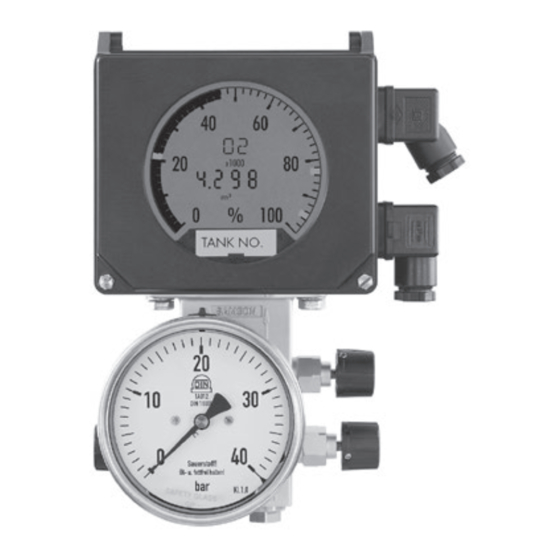
- Page 47 Display with operating elements Display mode: Gas code and operating state, Alarm A2 tank identifier Tank content % blinks Factor Alarm A1 blinks UCW blinks Depending on display mode: Tank content, MCN, SCN, Units for pressure Differential pres- SERIAL O inH sure and error INTERFACE mbar...
- Page 48 EB 9527-3 EN SAMSON AKTIENGESELLSCHAFT Weismüllerstraße 3 · 60314 Frankfurt am Main, Germany Phone: +49 69 4009-0 · Fax: +49 69 4009-1507 samson@samson.de · www.samson.de...
Need help?
Do you have a question about the Media 6 Z and is the answer not in the manual?
Questions and answers