Samson Media 6 Mounting And Operating Instructions
Differential pressure meter
Hide thumbs
Also See for Media 6:
- Mounting and operating instructions (34 pages) ,
- Mounting and operating manual (48 pages) ,
- Original instructions manual (40 pages)

Related Manuals for Samson Media 6


Summary of Contents for Samson Media 6
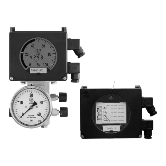
- Page 1 Differential Pressure Meter Media 6 Media 6 Z Media 6 with attached valve block Mounting and Operating Instructions EB 9527-3 EN Firmware V3.03 Edition February 2007...
-
Page 2: Table Of Contents
Arrangement of devices for flow rate measurement ... 12 Media 6 indicating unit ......12 Differential pressure lines . - Page 3 Contents Communication using the memory pen ....27 Exchanging data using the memory pen ....27 Communication using a PC .
- Page 4 Symbols Symbols used in these mounting and operating instructions Bold print indicates sections that require par- Bold print also indicates information and in- ticular attention. structions relating to safety. Note! Caution! Gives supplementary information and hints. Disobeying instructions may result in prop- erty damage.
- Page 5 The Media 6 Differential Pressure Meter is not approved for measuring flammable gases and liquids in Zone 0.
- Page 6 Filling limit during operation (UCW) gardless of the limit switches. A 2.10/B 2.10 A 2.11/B 2.11 Current output of Media 6 is set to ≤ 3.6 mA. Error code A2.11/B2.11 V3.02 Use the keys to switch the LCD on or off (“LCD ON” or “LCD OFF”).
- Page 7 Firmware changes Changes of the device's firmware compared to previous version EB 9527-3 EN...
-
Page 8: Design And Principle Of Operation
– Differential pressure measuring between changed on site between Media 6 and the flow and return flow pipe memory pen, and vice versa. – Pressure drop measuring on valves and... - Page 9 Connector A = 12 V to 36 V DC = 4 to 20 mA Min/max alarm A1 Connector B Min/max alarm A2 or pulse output in Media 6 Z Serial interface µP FRAM dp cell 1.1 Measuring diaphragm 1.2 Measuring springs dp cell 1.3 Lever...
-
Page 10: Technical Data
If the values remain below this span, the class accuracy of Class 2.5 may be exceeded Media 6 Z is equipped with one software switch A1 according to EN 60947-5-6 and one pulse output MCN = Max. Capacity Nominal (max. tank capacity); SCN = Save Capacity Nominal (capacity up to overflow) Difference of countswithin reading period ×... - Page 11 All pressures as gauge pressures · All errors and deviations in % of adjusted span Warning! Media 6 is not approved for measuring flammable gases and liquids in Zone 0! Devices intended for oxygen service are labeled The manufacturer has cleaned and assembled all devices for oxygen service under special con- ditions.
-
Page 12: Installation
VDE/VDI 3512 Sheet 1 for details. dius is 50 mm. Thoroughly flush the differential pressure lines 2.3 Media 6 indicating unit before connecting them to the device. Make sure that the high-pressure line is connected to Make sure that the high-pressure line is con-... - Page 13 Orifice plate assembly Equalizing tank Separation chamber Installation: Standard Standard Reverse Standard Reverse SAMSON valve blocks can be installed above the dp cell to match connections (+) to (+) and (–) to (–). Fig. 2 · Arrangement of devices EB 9527-3 EN...
-
Page 14: Orifice Plate Assembly
Do not install any control valves that con- When measuring the flow rate in liquids and stantly change the operating state of the pro- gases, the SAMSON valve block can also be cess medium (e.g. manually operated control mounted above the dp cell, so that the con- valves or temperature regulators) upstream of nection arrangement of (+) to (+) and (–) to (–) -
Page 15: Shut-Off And Equalizing Valves
2.5.3 Shut-off and equalizing suring point. valves 2.5.5 Accessories for connection As an alternative to the SAMSON valve block, the two shut-of valves as well as the by- The meters are delivered without screw fit- pass valve/equalizing valve can also be in- tings (oxygen versions are protected against stalled as illustrated in Fig. -
Page 16: Electrical Connection
(Test – +), see Fig. 10. The serial interface (see Fig. 10) is not approved for use in hazardous areas. As a result, use only the intrinsically safe SAMSON memory pen to transfer data. - Page 17 Electrical connection Connector A Media 6 Z includes only one software limit switch (Alarm 1) and one pulse output (at po- Two-wire connection for 4 to 20 mA signal. sition "Alarm 2"), which is proportional to the Permissible load R tank capacity, to control an external counter.
-
Page 18: Operation
≤ 1 mA Operation 4.1 Display and operating elements All necessary data and measured values saved in the memory of Media 6 are indicated on the LCD. The operating elements are located on the bottom panel behind the protective cover, which can... -
Page 19: Switching Display Mode
Operation 4.1.1 Switching display mode Depending on the operating mode, each pressing of the key allows you to switch between the standard display and up to eight other parameters. After eight seconds or after the marquee has finished scrolling, the display automatically returns to the default display. -
Page 20: Start-Up
Start-up Start-up 5.1 Liquid level measurement – For start-up observe Figs. 4 and 5 on page 15. 1. Open low-pressure line by slow turning. Initial position of the valves on the valve block 2. Close equalizing valve or bypass of the upon delivery: valve block. -
Page 21: Draining
Start-up Note! 5.3 Draining When using reverse installation, i.e. with the When measuring gas, drain condensed wa- meter mounted above the measuring point, ter from the equalizing tanks from time to the differential pressure lines may partly get time. drained when depressurizing the system. When starting up the system again, vent the Warning! arranged measuring system, allowing it to fill... -
Page 22: Adjustment
Adjustment Adjustment 6.1 Write protection 6.2 Selecting gas type The device includes two write-protection func- Select the desired type of gas according to the tions: positions for switches 1 and 2 as given in Fig. 7 and the table below. WRITE PROTECTION to prevent that operat- ing data are changed unintentionally. -
Page 23: Checking Zero
Adjustment Reactivate write protection by setting 6.3 Checking zero switch 4 to position ON. To check zero at atmospheric pressure, make sure that the pressures in both measuring Correction when tank is filled chambers are identical. This means that, with Zero can also be checked while the system is a differential pressure of Δp = 0 mbar, the running, provided the differential pressure... -
Page 24: Checking The Measuring Range (Span)
Adjustment For devices in oxygen service, make absolutely sure that the test medium is Warning! free of oil and grease. mA display Supply unit x1000 – – + Network Supply pressure reducing station with oil filter and test – pressure gauge Only use oil-free air or Test pressure other gases, e.g. -
Page 25: Setting The Limit Switches
Adjustment Press and hold key until display shows Note! currently measured value. Current signal I To calibrate the currently used gas, its display indicates current value in mA. value must be at least 85 % of the adjusted Press key to calibrate the span. Current upper measuring range value Δ... -
Page 26: Alarm Contacts A1 And A2
Press and hold keys until, after Note! approx. 3 s, the LCD is either switched ON or In counting flow rate mode (Media 6 Z), only OFF. alarm A1 is available. 6.7 Ammeter function Both limit switches are preset by the software To check the function of connected devices, to function as either min or max alarms. -
Page 27: Communication Using The Memory Pen
"read and write" status sponding to the tank type and associated gas Plug memory pen into serial interface. data to be transferred to Media 6 devices on MEMWR is indicated at the top of the display. site without requiring a PC/notebook PC sim-... -
Page 28: Communication Using A Pc
Transfer data from the memory pen to 7.2 Communication using a PC Media 6, "read only" status Media 6 can also be operated using a PC/ Deactivate write protection by setting notebook PC connected to the serial interface switch 4 to position OFF. -
Page 29: Troubleshooting
Errors are not saved; only the current error Press key to reset or confirm errors. switches the device to error mode. Depending on the error class, Media 6 re- For errors in Classes E1 and E2, the signal sponds differently when the key is pressed: current is set to ≤... - Page 30 Span error (error code 8) or error in tank characteristic (error code 16) Troubleshooting using memory pen If available, use a SAMSON memory pen to transfer new data to the device while the error is suppressed (approx. 8 s). Troubleshooting using PC or notebook PC...
-
Page 31: Servicing Explosion-Protected Devices
Servicing explosion-protected devices Servicing explosion-protected devices If a part of Media 6 on which the explosion protection is based needs to be serviced, the device must not be put back into operation until an expert has inspected it according to explosion pro- tection requirements, has issued a certificate stating this or given the device a mark of confor- mity. -
Page 32: Dimensions In Mm
Dimensions in mm Dimensions in mm 141.5 Pressure sensor, depending on manufacturer 180.5 32.5 Control panel 25.5 Pressure gauge, depending on manufacturer Pressure gauge connections For NG 100 pressure gauge: G ½ B-LH male thread with G ½ coupling sleeve acc. to DIN 16283 and 12x2 O-ring For NG 63 pressure gauge: G ¼... -
Page 33: Index
Index Index Accessories ..... 14 EC type exam. certificate . . 35, 36, 37, 38 Accessories for connection ..15 Electrical connection. - Page 34 Index Nominal pressure....10 UCW ......25 Units .
-
Page 35: Ec Type Examination Certificates
EB 9527-3 EN... - Page 36 EB 9527-3 EN...
- Page 37 EB 9527-3 EN...
- Page 38 EB 9527-3 EN...
- Page 39 EB 9527-3 EN...
-
Page 40: Display With Operating Elements
Display with operating elements Display mode: Alarm A2 Gas code and operating Tank content % Factor blinks state, tank identifier Alarm A1 blinks UCW blinks Depending on display mode: Tank content MCN, SCN, UCW, differen- Units for tial pressure and SERIAL pressure O inH... - Page 42 SAMSON AG · MESS- UND REGELTECHNIK Weismüllerstraße 3 · 60314 Frankfurt am Main · Germany Phone: +49 69 4009-0 · Fax: +49 69 4009-1507 EB 9527-3 EN Internet: http://www.samson.de...
Need help?
Do you have a question about the Media 6 and is the answer not in the manual?
Questions and answers