Icom IC-M73 Instruction Manual
Hide thumbs
Also See for IC-M73:
- Instruction manual (56 pages) ,
- Service manual (36 pages) ,
- Instruction manual (56 pages)
Table of Contents
Advertisement
Quick Links
Download this manual
See also:
Service Manual
Advertisement
Table of Contents

Subscribe to Our Youtube Channel
Related Manuals for Icom IC-M73


Summary of Contents for Icom IC-M73
-
Page 1: Instruction Manual
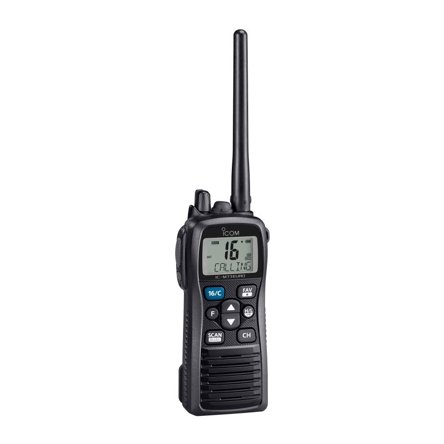
INSTRUCTION MANUAL VHF MARINE TRANSCEIVER iM73 iM73EURO This device complies with Part 15 of the FCC Rules. Opera- tion is subject to the condition that this device does not cause harmful interference. IC-M73 IC-M73EURO (These transceivers use the FA-S64V) -
Page 2: Important
FOREWORD FEATURES Thank you for purchasing this Icom product. The IC-M73/IC- Submersible construction VHF MARINE TRANSCEIVER M73EURO is designed and built Built tough to withstand the punishing marine environ- with Icom’s state of the art technology and craftsmanship. ment, the IC-M73/IC-M73EURO’s submersible construc-... -
Page 3: Precautions
Icom radios or Icom chargers. Only Icom battery packs and below –10°C (+14°F) or above +55°C (+131°F) for the AUS are tested and approved for use with Icom radios or charged with versions. Icom chargers. Using third-party or counterfeit battery packs or DO NOT chargers may cause smoke, fire, or cause the battery to burst. -
Page 4: Radio Operator Warning
ALWAYS keep the antenna at least 2.5 cm (1 inch) away from the body Electromagnetic Fields. when transmitting and only use the Icom belt clip which is listed on page 43 when attaching the radio to your belt, etc., to ensure FCC and IC RF exposure compliance requirements are not exceeded. -
Page 5: Avertissement Pour Les Opérateurs Radio
Interférence électromagnétique et compatibilité et d’IC en matière d'exposition aux RF sans fil; attache pour ceinture (MB- En mode de transmission, votre radio Icom produit de l'énergie de RF qui 103), bloc-piles rechargeable au lithium-ion (BP-245H). peut provoquer des interférences avec d'autres appareils ou systèmes. Pour CAUTION éviter de telles interférences, mettez la radio hors tension dans les secteurs... -
Page 6: Fcc Information
France Slovakia Germany Slovenia CAUTION: Changes or modifications to this device, not ex- Greece Spain pressly approved by Icom Inc., could void your authority to Hungary Sweden operate this device under FCC regulations. Iceland Switzerland Ireland Turkey... -
Page 7: In Case Of Emergency
IN CASE OF EMERGENCY RECOMMENDATION If your vessel requires assistance, contact other vessels and CLEAN THE TRANSCEIVER THOROUGHLY WITH FRESH the Coast Guard by sending a distress call on Channel 16. WATER after exposure to saltwater, and dry it before opera- tion. -
Page 8: Table Of Contents
TABLE OF CONTENTS FOREWORD ..................i DUALWATCH/TRI-WATCH ............IMPORTANT ..................i Description ................16 EXPLICIT DEFINITIONS ..............i Operation ................16 FEATURES ..................i 7 FUNCTION MODE OPERATION ........7–24 PRECAUTIONS ................ii About the function mode ............17 RADIO OPERATOR WARNING ............iii Manual recording function (Depending on versions) .....18 AVERTISSEMENT POUR LES OPÉRATEURS RADIO .... -
Page 9: Operating Rules
OPERATING RULES D Priorities A Restricted Radiotelephone Operator Permit is the license most often held by small vessel radio operators when a radio and keep an up-to-date copy handy. Safety and distress is not required for safety purposes. calls take priority over all others. If required, the Restricted Radiotelephone Operator Permit on another channel. -
Page 10: Supplied Accessories And Attachments
SUPPLIED ACCESSORIES AND ATTACHMENTS Supplied accessories Attachments D Flexible antenna Connect the supplied flexible Handstrap Battery Charger Belt clip antenna to the antenna connector. (with two screws) (with two screws) CAUTION: carry the transceiver by holding the antenna. may damage the transceiver. Li-ion battery pack Flexible antenna* D Handstrap... -
Page 11: D Battery Pack
SUPPLIED ACCESSORIES AND ATTACHMENTS D Battery pack D Belt clip Attach the belt clip to the transceiver. Attach the battery pack into the transceiver. Supplied screws Battery pack Lock the battery pack with the latch. Latch CAUTION: NEVER remove or attach the battery pack when the trans- ceiver is wet or soiled. -
Page 12: Panel Description
PANEL DESCRIPTION Front, top and side panels q VOLUME CONTROL [VOL] Turns ON power and adjusts the audio level. w PTT SWITCH [PTT] Hold down to transmit; release to receive. e MONITOR KEY [ Function held down. (p. 12) display (p. 6) [Z]. - Page 13 PANEL DESCRIPTION (pp. 14, 15) second. (p. 12) (p. 16) u CHANNEL/WEATHER CHANNEL KEY channels, while ignoring untagged channels, in a channel channel* when pushed. (pp. 9, 10) group. (p. 15) channel group* when held down for 1 second. (p. 9) channel as a Favorite (TAG) channel.
-
Page 14: Function Display
PANEL DESCRIPTION Function display r DUALWATCH/TRI-WATCH ICONS (p. 16) “DUAL” blinks during dualwatch; “TRI” blinks during tri- watch. t DUPLEX ICON (p. 9) Appears when a duplex channel is selected. y MONITOR ICON (p. 12) Appears when the monitor function is activated. u AUTOMATIC RECORDING ICON (p. -
Page 15: Panel Description
PANEL DESCRIPTION !1 ATIS ICON (pp. 9, 23) !7 BUSY ICON (pp. 11, 12) Appears when the channel group, in which ATIS function Appears when a signal is received, or the squelch opens. is activated, is selected or while programming an ATIS code. -
Page 16: Basic Operation
BASIC OPERATION Channel selection D Call channel IMPORTANT!: Prior to using the transceiver for the first time, fully charge the battery pack. This will help maximize Each regular channel group has separate leisure-use call the capability and life of the battery. To avoid damage to channels. - Page 17 BASIC OPERATION D U.S.A., International, Canadian and ATIS For Dutch ver ion channels The transceiver has U.S.A.* , International, Canadian* Hold down ATIS* channels. You must select the proper channels for the operating area. for 1 second Only USA, UK, EXP, CHN and AUS versions. ATIS channels International channels Only USA, EXP and CHN versions.
-
Page 18: Weather Channels
BASIC OPERATION D Weather channels The transceiver has 10 pre-programmed weather channels*. These are used for monitoring broadcasts from NOAA (Na- tional Oceanographic and Atmospheric Administration.) The transceiver can automatically detect a weather alert tone on the selected weather channel or while scanning. See the “SET mode items”... -
Page 19: Receiving And Transmitting
BASIC OPERATION Receiving and transmitting IMPORTANT: To maximize the readability of your transmit- CAUTION: Transmitting without an antenna may damage ted signal, pause a second after pushing [PTT]. Hold the the transceiver. microphone 5 to 10 cm from your mouth, and (2 to 4 inches) speak at your normal voice level. -
Page 20: Call Channel Programming
BASIC OPERATION Call channel programming Lock function The Call channel key is used to select Channel 9* by default. This function electronically locks all keys (except for [PTT], However, you can program your most often-used channel in to prevent accidental channel changes and each channel group for quick recall. -
Page 21: Adjusting The Squelch Level
BASIC OPERATION Adjusting the squelch level AquaQuake water draining function To adjust the transceiver’s squelch level, use the [Y]/[Z] The AquaQuake water draining function clears water away keys, as described below. In order to properly receive signals, from the speaker grill. Without this function, water may muffle as well as for the scan to function effectively operate, the the sound coming from the speaker. -
Page 22: Scan Operation (Except For The Dutch Version)
SCAN OPERATION Scan types Set the Favorite channels before scanning. Scanning is an efficient way to quickly locate signals over a (scanned channel) Clear those Favorite channels which are not needed or incon- wide frequency range. The transceiver has a priority scan set- veniently stop scanning, such as digital communications. -
Page 23: Setting Favorite Channels
SCAN OPERATION (Except for the Dutch version) Setting Favorite channels Starting a scan For more efficient scanning, add desired channels as Favorite First, set the weather alert function, priority scan function, scan resume timer and auto scan function, using the SET channels, or clear the Favorite for unwanted channels. -
Page 24: Dualwatch/Tri-Watch
DUALWATCH/TRI-WATCH Description Operation q Select a desired operating channel. Dualwatch monitors Channel 16 while you are receiving w Hold down on another channel; Tri-watch* monitors Channel 16 and the for 1 second to start Dualwatch call channel while receiving on another channel. or Tri-watch (depending on the SET mode setting;... -
Page 25: Function Mode Operation
FUNCTION MODE OPERATION About the function mode D Entering the function mode ‡ There are 7 transceiver functions in the function mode: Play [F] to enter the function mode. ‡ ‡ Push back function , Manual recording function , Automatic record- ‡... -
Page 26: Manual Recording Function (Depending On Versions)
FUNCTION MODE OPERATION q Push [F] to enter the function mode, You can record the received signal whenever you want by us- ing the manual recording function. and then push [Y]/[Z] to select the This function can record the received signal for maximum 30 manual recording function. -
Page 27: Automatic Recording Function (Depending On Versions)
FUNCTION MODE OPERATION When this function is turned ON, the transceiver automati- Push [F] to enter the function cally records the received signal into the memory. mode, and then push [Y]/[Z] to The maximum recording time is 60 seconds. select the automatic recording function. -
Page 28: Play Back Function (Depending On Versions)
FUNCTION MODE OPERATION This transceiver has two voice recorders. Push [F] to enter the function mode. One is the manual recording function which can record for 30 Push to enter the play back selection mode, seconds. The other is the automatic recording function which and then push [Y]/[Z] to select the desired play back can record the last 60 seconds of the receiving signal. -
Page 29: Channel Naming Function
1 second nel in use, or station names. to select a channel group, if necessary. When shipped from the factory, the IC-M73/IC-M73EURO is Push [F] to enter the function mode, programmed with default names for each VHF marine chan- and then push [Y]/[Z] to select the nel. -
Page 30: Opening Comment Entry Function
The opening comment appears each , moves to left. time the IC-M73/IC-M73EURO is powered ON. The comment Continue until the desired charac- may be up to 16 characters long. ters have been entered, then push You can use same characters as “Channel naming function.”... -
Page 31: Atis Code Programming (For Only The Dutch And German Versions)
FUNCTION MODE OPERATION ATIS code programming The 10-digit ATIS code can be programmed and confirmed After inputting the 10-digit ATIS with the following operation. code, push to write The ATIS code programming is not necessary and con- the code into the memory, then firmation can only be performed when the ATIS code has goes to the ATIS code confirma- been programmed by your dealer. -
Page 32: Backlight Function
FUNCTION MODE OPERATION Backlight function This function is convenient for nighttime operation. The back- lighting can also be turned OFF in the SET mode. (p. 27) Push any key other than [PTT] to turn ON the backlighting. inactivity. Push [F] to enter the function mode, and then push [Y]/[Z] to select the backlighting function. -
Page 33: Set Mode
SET MODE SET mode programming D SET mode operation The SET mode is used to change the status of 17 transceiver † † functions : Beep tone function, Weather alert function , Prior- Turn OFF power. w While holding down [ ity scan, Scan resume timer, Auto scan start function, Dual/ ] , turn ON power to enter the SET Tri-watch function, Monitor key action, Display backlight, LCD... -
Page 34: Set Mode Items
“ ” weather announcements. When the weather alert function is turned ON, any detected weather alert will make the IC-M73/ Except for the HOL version, the scan resume timer can be set IC-M73EURO activate a blinking “ ” alert icon on the as a pause (OFF) or timer scan (ON). -
Page 35: Auto Scan Function
SET MODE D Auto scan function D Monitor key action “ ” “ ” Except for the HOL version, the auto scan function automati- The monitor key action temporarily cuts off the squelch func- cally starts the desired scan when no signal is received, and tion. -
Page 36: Lcd Contrast Selection
SET MODE D LCD contrast selection D Channel name scroll type “ ” “ ” The contrast of the LCD can be set to Hi (default) or Lo. Set the channel name/comment scroll type to 1 or 2. then scrolls. When the channel name or comment is 7 character or less, it does not scroll (default). -
Page 37: Rx Noise Cancel Function
SET MODE D RX Noise Cancel function D RX bass boost function “ ” “ ” Set the Noise Cancel function for reception. The function may not be Set the bass boost function for reception. The function may not available, depending on the transceiver version. be available, depending on the transceiver version. - Page 38 SET MODE D Automatic recording threshold level “ ” Set the automatic recording threshold level. The function may not be available, depending on the transceiver version. Set the threshold level to shallow. Weak signals will automatically be recorded into memory. Set the threshold level to mid.
-
Page 39: Battery Charging
R DANGER! Use and charge only specified Icom battery R DANGER! NEVER solder the battery terminals, or NEV- pack with Icom transceiver. Only Icom battery pack is tested ER modify the battery pack. This may cause heat genera- and approved for use with Icom transceiver. Using third- tion, and the battery may rupture, emit smoke or catch fire. - Page 40 fied temperature range: +10˚C to +40˚C (+50˚F to +104˚F). tended period of time. If the battery must be left unused for a Icom recommends charging the battery at +20˚C (+68˚F). long time, it must be detached from the radio after discharg- The battery may heat up or rupture if charged out of the ing.
-
Page 41: Supplied Battery Charger
BATTERY CHARGING Supplied battery charger D Charging Connect the AC adapter as shown below. Insert the battery pack with or without the transceiver into Supplied screws Supplied screws the charger. e Charge the battery pack approximately 3 hours, depend- ing on the remaining power level. Tran ceiver OPC-515L* (for a Turn... -
Page 42: Optional Battery Chargers
BATTERY CHARGING Optional battery chargers Connect the 8-pin connector of the each charger slot to the AD-129 desktop charger adapter’s plug. The optional BC-197 with the BC-157S will simultaneously Install the adapter into the each charger slot in the direc- charge up to 6 Li-ion battery packs. -
Page 43: Optional Swivel Belt Clip
OPTIONAL SWIVEL BELT CLIP Attaching Detaching Screw the base clip to the Turn the transceiver upside down in the direction of the back of the transceiver us- arrow and pull out from the belt clip. Supplied screws ing the two screws (sup- , as shown to the right. -
Page 44: Optional Speaker-Microphone
OPTIONAL SPEAKER-MICROPHONE Attaching HM-202 is also an optional speaker microphone. see the Insert the speaker-mic connector onto the [SP MIC] connec- page 43 for details. tor and carefully screw it tight, as shown in the diagram below. Be careful not to cross-thread the connection. Alligator type clip To attach the speaker-microphone Set the triangle mark... -
Page 45: Troubleshooting
TROUBLESHOOTING PROBLEM POSSIBLE CAUSE SOLUTION REF. The transceiver does not pp. 33, turn ON. p. 3 No sound from the speak- p. 13 [VOL] to set a suitable level. p. 11 [F] to drain water from the speaker. p. 13 [SP MIC] connector. -
Page 46: Specifications
SPECIFICATIONS D General Spurious response rejection ratio : 70 dB (typical) : 70 dB (typical) : Rx 156.050–163.275 MHz 8 ˘ load) : 0.35 W typical (External) –4°F to +140°F) : 0.7 W typical (Internal) (approximately) Max. audio 0.45 A 7.4 V DC nominal (negative ground) D General ˘... - Page 47 SPECIFICATIONS D Transmitter 7.4 V DC nominal (negative ground) *German version only ˘ nominal 125(H) 30(D)mm modulation : 2.0(W) 4.9(H) 1.2(D) inches (Projections not included) (approximately) : 280 g/9.9 oz with BP-245H : 0.25 μW D Transmitter Receiver : 5 W/3 W/1 W : –4 dBμ...
-
Page 48: Vhf Marine Channel List
VHF MARINE CHANNEL LIST Frequency (MHz) Frequency (MHz) Frequency (MHz) Frequency (MHz) Frequency (MHz) Frequency (MHz) Transmit Receive Transmit Receive Transmit Receive Transmit Receive Transmit Receive Transmit Receive 156.050 160.650 156.550 156.550 157.050 161.650 156.075 160.675 156.575 156.575 157.075 161.675 156.100 160.700 156.600... - Page 49 VHF MARINE CHANNEL LIST hannel (for U.K. version only) Frequency (MHz) Frequency (MHz) Frequency (MHz) Frequency (MHz) Frequency (MHz) Frequency (MHz) Transmit Receive Transmit Receive Transmit Receive Transmit Receive Transmit Receive Transmit Receive 156.050 156.050 156.600 156.600 157.100 157.100 156.225 156.225 75 * 156.775...
- Page 50 VHF MARINE CHANNEL LIST CAN Tran mit Receive CAN Tran mit Receive CAN Tran mit Receive CAN Tran mit Receive 156.050 160.650 157.050 161.650 156.425 156.425 157.325 157.325 156.050 156.050 21A 157.050 157.050 156.475 156.475 157.375 161.975 156.100 160.700 Rx only 161.650 RX only 156.525 157.375 157.375 156.150 160.750...
-
Page 51: Options
Icom transceiver. Icom is not responsible replace it with a new for the destruction or damage to an Icom transceiver in the event the rated fuse. DO NOT Icom transceiver is used with equipment that is not manufactured or... -
Page 52: Index
INDEX – A – Charging caution ................32 About the function mode ..............17 COUNTRY CODE LIST ..............v AD-129 installation .................34 – D – Adjusting the squelch level .............13 DC CABLES ...................43 AquaQuake water draining function..........13 Description..................16 ATIS code confirmation..............23 Detaching ..................35 ATIS code programming ..............23 Dual/Tri-watch function ..............27 Attaching ...................35, 36... - Page 53 INDEX – M – RX bass boost function ..............29 Manual recording function ..............18 RX Noise Cancel function ...............29 Monitor function ................12 – S – Monitor key action................27 SCAN OPERATION ................14 – N – Scan resume timer .................26 NORMAL SCAN ................14 Scan types ..................14 Scrolling speed ................28 –...
- Page 54 MEMO...
- Page 55 MEMO...
- Page 56 < Intended Country of U e > A-7070D-1EX-e Printed in Japan 2013–2014 Icom Inc. © 1-1-32 Kamiminami, Hirano-ku, Osaka 547-0003, Japan Printed on recycled paper with soy ink.
Need help?
Do you have a question about the IC-M73 and is the answer not in the manual?
Questions and answers