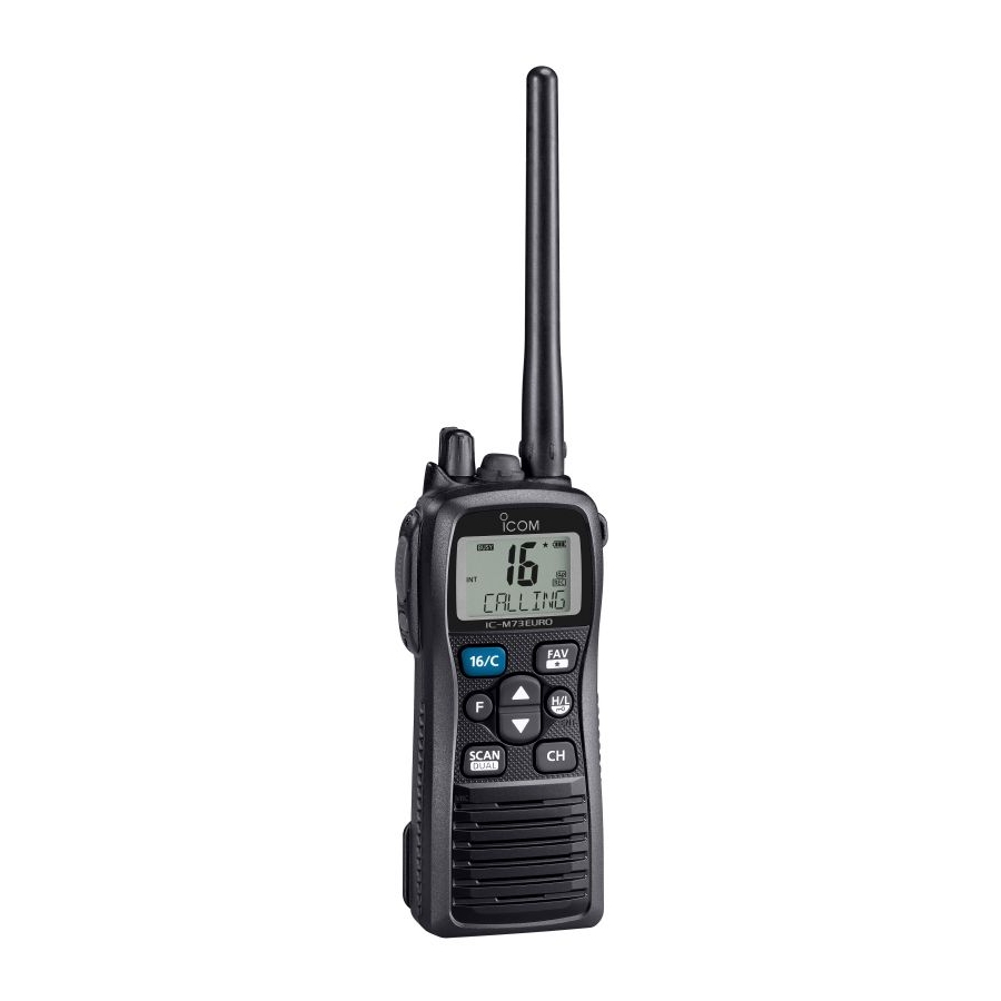
Icom IC-M73 Service Manual
Vhf marine transceiver
Hide thumbs
Also See for IC-M73:
- Instruction manual (56 pages) ,
- Instruction manual (56 pages) ,
- Instruction manual (56 pages)
Table of Contents
Advertisement
Advertisement
Table of Contents

Related Manuals for Icom IC-M73


Summary of Contents for Icom IC-M73
- Page 1 VHF MARINE TRANSCEIVER S-14919XZ-C1 April 2013...
- Page 2 8. READ the instructions of the test equipment thoroughly before connecting it to the transceiver. Icom, Icom Inc. and the Icom logo are registered trademarks of Icom Incorporated (Japan) in Japan, the United States, the United Kingdom, Germany, France, Spain, Russia and/or other countries.
- Page 3 TABLE OF CONTENTS SECTION SPECIFICATIONS SECTION INSIDE VIEWS SECTION DISASSEMBLY INSTRUCTION SECTION CIRCUIT DESCRIPITON RECEIVER CIRCUITS ..................4-1 TRANSMITTER CIRCUITS ................4-2 FREQUENCY SYNTHESIZER CIRCUITS ............4-3 POWER SUPPLY CIRCUITS ................4-4 PORT ALLOCATIONS ..................4-4 SECTION ADJUSTMENT PROCEDURES PREPARATION ....................5-1 FREQUENCY ADJUSTMENT ................
-
Page 4: Specifications
SECTION 1. SPECIFICATIONS IC-M73EURO IC-M73 IC-M73EURO (AUS version) • Frequency coverage 156.025–157.425 MHz 156.000–161.450 MHz 156.025–157.425 MHz 156.050–163.275 MHz 156.000–163.425 MHz 156.300–162.025 MHz • Type of emission 16K0G3E 50 Ω (nominal) • Antenna impedance • Operating temperature range –20°C to +60°C –15°C to +55°C... -
Page 5: Inside Views
SECTION 2. INSIDE VIEWS • MAIN UNIT CPU CLOCK (X480) BACKLIT LED DRIVER (Q240) BUFFER (Q350) BUFFER (IC364) RESET IC (IC341) (IC360) EEPROM (IC340) CPU 5V (IC220) 2ND IF FILTER (FI170) AFV LINE CONTROL (Q230) AFV LINE CONTROL (Q231) AFV LINE CONTROL IF IC (Q401) (IC170) - Page 6 • RF UNIT (TOP VIEW) PLL IC (IC1) +3.3 V REGULATOR (IC2) BUFFER (Q3) APC AMP (IC50) TX MUTE SW (Q351) +5 V REGULATOR (Q222) • RF UNIT (BOTTOM VIEW) (FI151) (FI150) 1ST IF AMP (Q151) VCC LINE CONTROLLER REFERENCE (Q480) FREQUENCY OSCILLATOR...
- Page 7 SECTION 3. DISASSEMBLY INSTRUCTION 1. Removing the Front panel 2. Removing the MAIN UNIT 1) Remove 6 screws from the rear panel. 1) Remove 5 screws from the MAIN UNIT. Screw×2 Screw×5 Screw×4 MAIN UNIT MAIN UNIT MAIN UNIT MAIN UNIT MAIN UNIT CHASSIS 2) Disconnect 2 fl...
- Page 8 3. Removing the RF UNIT 1) Unsolder total of 7 points. UNSOLDER RF UNIT Solder remover CHASSIS 2) Remove 3 screws from the RF UNIT. 3) Remove the RF UNIT from the CHASSIS. Screw×3 RF UNIT CHASSIS 4 - 1...
- Page 9 SECTION 4. CIRCUIT DESCRIPTION 4-1 RECEIVE CIRCUIT • ANTENNA SWITCH (RF UNIT) • 1st IF CIRCUITS (RF UNIT) The received signal from the antenna connector are passed The received signal is converted into the 1st IF signal, and through the low-pass filter (LPF; L81, L82, C83−C86 and amplifi...
- Page 10 • AF CIRCUITS (MAIN UNIT) 4-2 TRANSMIT CIRCUITS The demodulated AF signal from the demodulator circuits is • MICROPHONE AMPLIFIER CIRCUITS amplifi ed and fi ltered in AF amplifi er circuits. (MAIN UNIT) The AF signal from the microphone (MIC signal) is fi ltered The demodulated AF signal from the IF IC (IC170, pin 9) is and level-adjusted at microphone amplifi...
-
Page 11: Frequency Synthesizer
• APC CIRCUIT (RF UNIT) 4-3 FREQUENCY SYNTHESIZER The APC (Automatic Power Control) circuit stabilizes trans- • VCO CIRCUIT (RF UNIT) mit output power to prevent transmit output power level The VCO (Q21, Q22, D20−D22) generates the both of trans- change which is caused by load mismatching or heat effect, mit signal and LO signal for the 1st IF conversion. - Page 12 4-4 POWER SUPPLY CIRCUITS 4-5 PORT ALLOCATIONS • CPU (MAIN UNIT: IC360) Line Description name Port Description Name The same voltage as attached battery pack. BEEP Beep sound to the AF circuits. Common 5 V converted from VCC line by the CPU5V regulator (IC220).
- Page 13 • CPU (MAIN UNIT: IC360) (continued) • D/A CONVERTER (RF UNIT: IC190) Port Port Description Description Name Name MODC Deviation adjustment. • While transmitting: MIC gain controller (Q450 and Q451) FCON Reference frequency adjustment. control. PCON Transmit power setting voltage. MIC1/ ( T h e m i c r o p h o n e s e n s i t i v i t y i s Attenuator (RF UNIT: D94) switching signal.
-
Page 14: Adjustment Procedure
SECTION 5. ADJUSTMENT PROCEDURE 5-1 PREPARATION ¤ REQUIRED EQUIPMENTS EQUIPMENT GRADE AND RANGE EQUIPMENT GRADE AND RANGE ADJ-M73 Modifi ed OPC-478UC and OPC-922 ADJUSTMENT SOFTWARE Cloning software JIG cable (Revision 1.0 or later) (See the illust below) Measuring range : 0.1–10 W Range : 0.1–300 MHz RF power meter... - Page 15 ¤ CONNECTION AC millivoltmeter Standard signal generator –20 to 90 dBµ (–127 dBm to –17 dBm) Audio generator OPC-478 (RS-232C type) to RS-232C port DO NOT transmit while an SSG is connected to OPC-478UC (USB type) the antenna connector. Attenuator to USB port 30 dB or more deviation meter...
- Page 16 5-2 SOFTWARE ADJUSTMENT (FREQUENCY ADJUSTMENTS) 1) Select an adjustment item using [↑]/[↓] on the PC's keyboard. 2) Set or modify the adjustment value as specifi ed using [←]/[→] on the PC's keyboard, and then push [ENTER]. MEASUREMENT ADJUSTMENT ADJUSTMENT CONDITION VALUE UNIT OPERATION...
- Page 17 5-3 SOFTWARE ADJUSTMENT (RECEIVE AND TRANSMIT) 1) Select an adjustment item using [↑]/[↓] on the PC’s keyboard. 2) Set or modify the adjustment value as specifi ed using [←]/[→] on the PC’s keyboard, and then push [ENTER]. MEASUREMENT ADJUSTMENT ADJUSTMENT CONDITION VALUE UNIT OPERATION...
-
Page 18: Parts List
SECTION 6. PARTS LIST [MAIN UNIT] [MAIN UNIT] PARTS PARTS DESCRIPTION DESCRIPTION LOCATION LOCATION IC170 1110008140 S.IC GT3136 <SEI> 51.2/33.0 D350 1750001810 S.DIO L1SS400T1G <SLVJ> 80.3/29.4 IC190 1110007550 S.IC R2A20178NP 51.4/11.6 D430 1750002020 S.DIO DA2S10100L 21.3/30.4 IC200 1110006350 S.IC LM2902PWR 29.7/33.6 D431 1750001850 S.DIO... - Page 19 [MAIN UNIT] [MAIN UNIT] PARTS PARTS DESCRIPTION DESCRIPTION LOCATION LOCATION R275 7030005050 S.RES ERJ2GEJ 103 X (10K) 32.7/15.4 R554 7410001220 S.ARR EXB28V103JX [USA-10] B 14.9/21.8 R276 7030006610 S.RES ERJ2GEJ 394 X (390K) 31.9/17.6 7410001220 S.ARR EXB28V103JX [EXP-10] R277 7030005090 S.RES ERJ2GEJ 104 X (100K) 31.9/19.2 7410001220 S.ARR EXB28V103JX [EUR-11]...
- Page 20 [MAIN UNIT] [MAIN UNIT] PARTS PARTS DESCRIPTION DESCRIPTION LOCATION LOCATION R575 7030005120 S.RES ERJ2GEJ 102 X (1K) [USA-10] B 73.4/22.5 C286 4550007520 S.TAN F931A106MAABMA 32.9/12.7 7030005120 S.RES ERJ2GEJ 102 X (1K) [EXP-10] C287 4030017700 S.CER C1005 CH 1H 151J-T 35.9/7.8 7030005120 S.RES ERJ2GEJ 102 X (1K) [EUR-11] C288...
- Page 21 [MAIN UNIT] [MAIN UNIT] PARTS PARTS DESCRIPTION DESCRIPTION LOCATION LOCATION C526 4030016930 S.CER C1005 JB 1A 104K-T [USA-10] B 24.7/24.2 C539 4030018860 S.CER C1005 JB 0J 105K-T [USA-10] B 25.7/27.4 4030016930 S.CER C1005 JB 1A 104K-T [EXP-10] 4030018860 S.CER C1005 JB 0J 105K-T [EXP-10] 4030016930 S.CER C1005 JB 1A 104K-T [EUR-11]...
- Page 22 [RF UNIT] [RF UNIT] PARTS PARTS DESCRIPTION DESCRIPTION LOCATION LOCATION 1130016080 S.IC GP214D <SEI> 7.3/35.3 7030004980 S.RES ERJ2GEJ 101 X (100) 5.8/10.6 1180003980 S.REG XC6221A332MR-G 12.3/29.4 7030005530 S.RES ERJ2GEJ 100 X (10) 5.5/6.0 IC50 1120002830 S.IC NJM2125F-TE1-#FZZB 22.4/22.3 7030007300 S.RES ERJ2GEJ 332 X (3.3K) 5.2/4.8 7030007570 S.RES ERJ2GEJ 122 X (1.2K) 4.2/7.2...
- Page 23 [RF UNIT] [RF UNIT] PARTS PARTS DESCRIPTION DESCRIPTION LOCATION LOCATION 4030017460 S.CER C1005 JB 1H 102K-T 16.6/13.8 6910014690 S.BEA MPZ1608S221A-T 15.4/15.0 4030016790 S.CER C1005 JB 1E 103K-T 14.1/13.7 6910014690 S.BEA MPZ1608S221A-T 18.3/13.4 4030017460 S.CER C1005 JB 1H 102K-T 11.4/3.8 4030017430 S.CER C1005 CH 1H 101J-T 12.3/5.1 4030017460 S.CER C1005 JB 1H 102K-T 14.3/2.6...
-
Page 24: Mic Unit
[MIC UNIT] [VR UNIT] PARTS PARTS DESCRIPTION DESCRIPTION LOCATION LOCATION C700 4030017420 S.CER C1005 CH 1H 470J-T 9.3/5.1 R801 7210003650 VAR F081-0028A <SLVJ> C703 4030017620 S.CER C1005 CH 1H 100C-T 8.0/6.6 J416 6510029480 S.CON 06FH-SM1-TB(LF)(SN) 4.1/2.0 J415 6510022692 S.CON 06FLT-SM2-TB(LF)(SN)(M) 8.2/2.5 J416 6510021941 CON... - Page 25 SECTION 7. MECHANICAL PARTS [CHASSIS PARTS] [RF UNIT] ORDER ORDER DESCRIPTION QTY. DESCRIPTION QTY. J101* 6510025121 30RF-JMCS-G-1B-TF (N) (LF) (SN) 6910017840 2905 ANT CONNECTOR <EIK> 6510025340 2905 CONTACT SPRING <CCP> S250* 2260002800 SW-167 (SKQTLAE010) S328* 2260002800 SW-167 (SKQTLAE010) 8210029010 3495 FRONT PANEL ASS.Y<ITM> [USA] 8210029010 3495 FRONT PANEL ASS.Y<ITM>...
- Page 26 [ACCESSORIES] ORDER DESCRIPTION QTY. (Optional) FA-S64V [USA] (Optional) FA-S64V [EXP] (Optional) FA-S59V [EUR-01] (Optional) FA-S64V [EUR] (Optional) FA-S64V [UK] (Optional) FA-S64V [FRG] (Optional) FA-S64V [HOL] (Optional) FA-S64V [AUS] (Optional) FA-S64V [USA-10] (Optional) FA-S64V [EXP-10] (Optional) FA-S59V [EUR-11] (Optional) FA-S64V [EUR-10] (Optional) FA-S64V [UK-10]...
- Page 27 MP27(C) MP11(C)×2 MP26(C) *; Location MP32(C) MP12(C) MP19(C) MP13(C) MP23(C) MP14(C) MP21(C) MP20(C) MP24(C) R801(V) VR UNIT MP37(C) MP1(MI)* MP43(C) J416(MI) W801(V) To J301 MP1(MI) MIC UNIT (MAIN UNIT) W470(MI) To J300 (MAIN UNIT) MP28(C)×2 MP29(C)×4 MP21(R) MP5(C) RF UNIT MP52(R) MP30(C) J3(C)
- Page 28 The combination of top side and bottom side of this SECTION 8. BOARD LAYOUTS • MAIN UNIT (TOP VIEW) J1 (CHASSIS) • RF UNIT (TOP VIEW) • MIC UNIT • VR UNIT (TOP VIEW) (TOP VIEW) B7817A MC250 J416 SP1 (CHASSIS) 8 - 1...
- Page 29 The combination of top side and bottom side of this • MAIN UNIT (BOTTOM VIEW) • RF UNIT (BOTTOM VIEW) FI151 FI150 • VR UNIT (BOTTOM VIEW) • MIC UNIT (BOTTOM VIEW) J416 PWON J415 J416 AFOUT EXDET VOLIN VOLO AFOUT EXTMIC J415...
- Page 30 SECTION 9. BLOCK DIAGRAM ANTENNA Q480: RSQ035P03TR IC1:GP214D Q21:2SC4226 D50:HVD144A Q50: Q53: Q54: Q22:2SC4226 Q23:2SC4215 Q24:2SC4215 D51:HVD144A KTC3770U RD01MUS2 RD07MUS2B D22:HVB350BYPTL BATT CTRL TEMP 3.3V PLL IC LOOP TX/RX BUFF BUFF BUFF DRIVE IC2:XC6221A332MR Q20:LDTC144EE IC50:NJM2125F D91: X1:CR-766 Q3:2SK880 D20,D21:HSC277TRF Q25:2SC4215 Q100:LDTC144EE RB706F...
- Page 31 SECTION 10. VOLTAGE DIAGRAM • RF UNIT TX:2.72V TX:3.27V RX:2.80V RX:3.33V TXMS TX:4.60V RX:0.00V VOUT MPZ1608S221A MPZ1608S221A XC6221A332MR TX:0.69V LDTA144EE RX:1.29V Q351 Fin1 Fin2 1SV307 UNLK 2SC4215 2.7U 6.8N 0.001 45.3N 0.001 0.001 27.2N L1SS400 4.7k HVD144A LDTC144EE 2SC4215 OSCI C225 SDATA 2SC4226...
- Page 32 • MAIN UNIT (1/2) PCON R192 MODCO IC190 IC200 LM2902PWR 1 VIN2 VIN7 2 VDD IC432 3 LD DAST 1.86V LM2904PWR IC431 RESET 4 CLK SCLK LM2904PWR VDAREF2 R562 R563 5 DI SDATAO VDAREF1 6 VIN3 VIN6 4.7k LM2904PWR IC432 R2A20178 NOISV R160...
- Page 33 • MAIN UNIT (2/2) J301 J300 BATTV Q225 L2SA1576AS R173 R170 KTA1664 Q221 5.00V DS480 R222 R227 L2-1365TVF IC220 1 VIN VOUT Q224 2 GND FI170 LTWC450E1 IC170 KTC811U 3 CTRL C171 1 OSCIN MIXIN 2 OSCOUT NJU7772F05 C190 3 MIXOUT N-REC 4 VCC IC360...
- Page 34 Highway 17 Delta, B.C., V4K 5B8, Canada : http://www.icomspain.com Phone : +1 (604) 952-4266 Fax : +1 (604) 952-0090 E-mail : icom@icomspain.com : http://www.icomcanada.com E-mail : info@icomcanada.com Blacksole House, Altira Park, Herne Bay, Kent CT6 6GZ, UK Phone : +44 (0) 1227 741741...
- Page 35 S-14919XZ-C1 1-1-32, Kamiminami, Hirano-ku, Osaka 547-0003, Japan © 2013 Icom Inc.
Need help?
Do you have a question about the IC-M73 and is the answer not in the manual?
Questions and answers