Table of Contents
Advertisement
Quick Links
www.aeroplusrc.com
Item No:A-G120001
Specs:
WING SPAN:
LENGTH:
WING AREA:
FLYING WEIGHT:
ENGINE:
RADIO:
Description
Covering Material
Carbon Fibre:
H-G120001A
ORACOVER FERRARI RED 21-023#
ORACOVER WITH
ORACOVER BLACK
ORACOVER SILVER
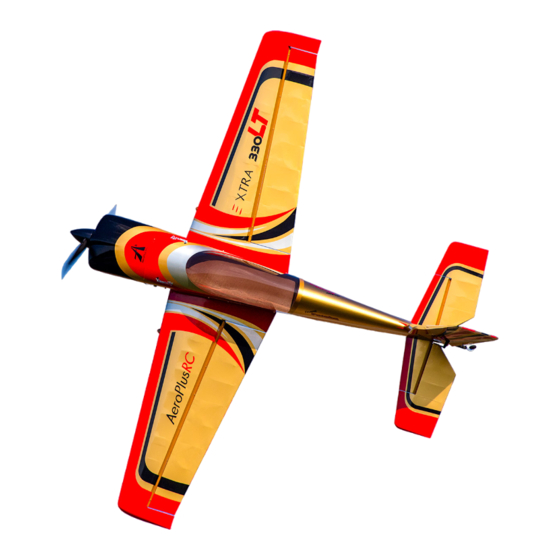
Extra 330LT
111" (2833mm)
100" (2530mm)
2139sq in (138sq dm)
25.3-28lbs (11500-12800g)
100cc-120cc gas
4CH/6-9S
Genuine Oracover
Spinner, wing tube and sleeves, landing gear, tail gear;
Fibreglass servo arms, horn and reinforced U/C mounting
Fiberglass servo arms and horn;
Built-in tuned pipe or canister tunnel;
Removable Wings, Stabs and Rudders;
Carbon fibre rods to make the wings and fuselage light weight and strong;
Alu hub Wheels; Adjustable pushrods;
Two piece clamshell cowl, Ringed Cowl
Extra covering provided for small repairs
Pre drilled hinges
21-010#
21-071#
21-091#
AeroPlus RC Copyright 2014 © All Rights Reserved
85-125CC
2 Colour schemes
H-G120001B
ORACOVER FERRARI RED 21-023#
ORACOVER GOLD
ORACOVER BLACK
ORACOVER SILVER
service@aeroplusrc.com
21-092#
21-071#
21-091#
Advertisement
Table of Contents

Related Manuals for AeroPlus Extra 330LT


Summary of Contents for AeroPlus Extra 330LT
- Page 1 Pre drilled hinges 2 Colour schemes H-G120001A H-G120001B ORACOVER FERRARI RED 21-023# ORACOVER FERRARI RED 21-023# ORACOVER WITH 21-010# ORACOVER GOLD 21-092# ORACOVER BLACK 21-071# ORACOVER BLACK 21-071# ORACOVER SILVER 21-091# ORACOVER SILVER 21-091# AeroPlus RC Copyright 2014 © All Rights Reserved...
- Page 2 100-125CC Extra 330LT Congratulations on your purchase of your new AeroPlus RC Extra 330LT. This plane has been designed to be one of the lightest and highest performance aerobatics planes anywhere. We hope that you will enjoy this plane and will exceed your expectations in what a model airplane can be.
-
Page 3: Landing Gear Assembly
Note- you must place the washer now as it will be impossible to place once the axle is tightened. I use plastic servo horns drilled out in place of wood spacers for durability. AeroPlus RC Copyright 2014 © All Rights Reserved... - Page 4 This method takes time but is worth it as the wheel pants will last many flights. Horizontal Stab 1. Now glue the control horns into the elevators. a. First use a sharp hobby knife to remove the covering from the slots. AeroPlus RC Copyright 2014 © All Rights Reserved...
- Page 5 Note. Servo fits so spline is towards the front of the plane. b. Now pre drill the servo mounts with a 1/16 drill bit, the secure the servo into the servo mount with servo hardware. AeroPlus RC Copyright 2014 © All Rights Reserved...
- Page 6 Note. Depending on servo arms used it may be necessary to install arm before reinstalling the servo. d. Next install the servo linkages. 3. Extensions a. Thread a 36” servo extension though the fuselage to the openings near the elevator. AeroPlus RC Copyright 2014 © All Rights Reserved...
- Page 7 Note: make sure the servo wire goes cleanly inside the fuselage and is not pinched. c. Attached the elevator half to the fuselage with the provided hardware. M3×12 inner hexagon screw & M3 wrench 5. Repeat the process for the other elevator half. AeroPlus RC Copyright 2014 © All Rights Reserved...
- Page 8 3. Sand the area on the horn that fits inside the rudder so the glue bonds better. 4. Attaching the rudder. a. Insert the easy removal pin into the pin hinges. AeroPlus RC Copyright 2014 © All Rights Reserved...
- Page 9 Fit the rudder servo and drill holes using a 1/16 drill bit for the servo screws, then drop thin C.A. glue into the holes to strengthen the wood. Note: besure the glue has fully cured before installing the servo again. AeroPlus RC Copyright 2014 © All Rights Reserved...
- Page 10 Thread the cables though the fuselage from the rudder to the servo tray b. Loop the cable though the crimp and attachment point as shown below. c. Crimp the cable using a pair of pliers then trim cable. AeroPlus RC Copyright 2014 © All Rights Reserved...
- Page 11 1. Locate all parts in picture below, when assembling remember to use thread-lock on all parts 2. Assemble gear according to photograph. 3. Before glueing in till mount be sure to slip tiller mount over tiller rod. AeroPlus RC Copyright 2014 © All Rights Reserved...
- Page 12 1. The ailerons on the wings are pre-glued. Check each one by gently pulling to make sure that they are secure 2. Installing aileron control horns a. Remove the covering where the aileron horns are glued in place. Use either a soldering iron or a sharp knife AeroPlus RC Copyright 2014 © All Rights Reserved...
- Page 13 Repeat for all 4 aileron control horns. 3. Install Aileron Servos a. First test fit the servo into the servo mount. Some trimming make be required. Note. Servo fits so spline is towards the front of the plane. AeroPlus RC Copyright 2014 © All Rights Reserved...
- Page 14 Next remove the servo and use thin C.A. glue to reinforce the threads. After the glue is dry reinsert the servo. d. If required install a servo extension lead onto the servo, remember to use a servo plug clip or heat shrink AeroPlus RC Copyright 2014 © All Rights Reserved...
- Page 15 Repeat on other wing Note: On wings using two servos be sure the servos are not binding. If the are you make have to adjust linkages or use a product such as a match box AeroPlus RC Copyright 2014 © All Rights Reserved...
- Page 16 The difference will be the standoff length needed. 3. Exhaust options. The plane is equipped with a pipe tunnel so it will accommodate many kinds of exhaust including stock, cans, and pipes. AeroPlus RC Copyright 2014 © All Rights Reserved...
- Page 17 To make sure the engine stays cool. Ensure that enough air can get out of the cowl. The ration is usually 3 to 1. With the exit being 3 times larger then the intake. 5. Attach gas proof tube such as Tygon according to the labelling on tank AeroPlus RC Copyright 2014 © All Rights Reserved...
- Page 18 7. Install the engine box cover plate once all connections have been made for the engine. 8. Mount the engines ignition to the motor box on radio foam to reduce vibrations. AeroPlus RC Copyright 2014 © All Rights Reserved...
- Page 19 2. A convenient place to mount the RX is just in front of the rudder servo. Ensure that it is mounted on Velcro or radio foam and securely strapped down. Canopy Attachment 3. The canopy is held in place with the 4 screws, ensure these are tight before flying AeroPlus RC Copyright 2014 © All Rights Reserved...
-
Page 20: Before You Fly
CG Location We suggest for initial test flights set the CG 172mm or 6 3/4 inches from the leading edge of the wing. Adjust after first flights to personal preference. Enjoy flying! AeroPlus RC Copyright 2014 © All Rights Reserved... - Page 21 Pictures AeroPlus RC Copyright 2014 © All Rights Reserved...
Need help?
Do you have a question about the Extra 330LT and is the answer not in the manual?
Questions and answers