Advertisement
Quick Links
www.aeroplusrc.com
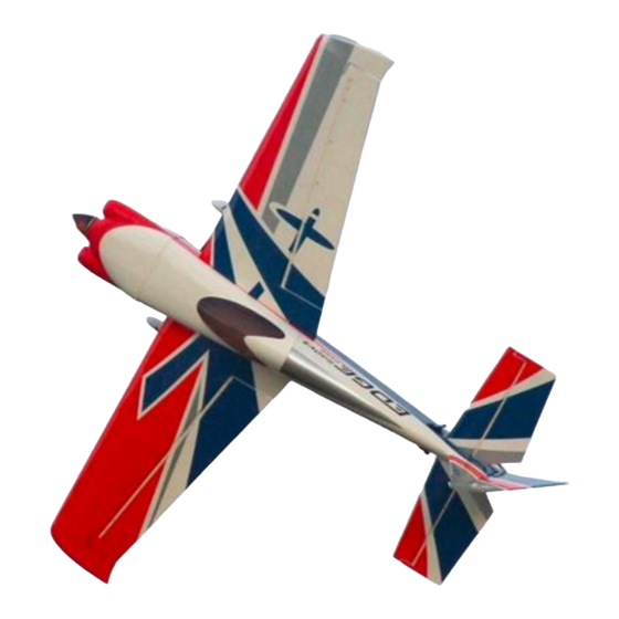
Edge 540 V3 20CC
Item No:L-G035016
Specifications
Wing Span
Length
Wing Area
Flying Weight
Glow
Gasoline
Electric
Radio
Description
67"(1700mm)
65"(1649mm)
907sq in(58.5sq dm)
7-7.7lbs(3000-3300g)
75-.91(2C) .91-1.10(4C)
20-26cc gas
AXI 55030 5-6S Lipo
4CH/5-6 servos
Carbon Fibre : Wing tube and sleeves, landing gear, tail gear;
Fibreglass servo arms, horn and reinforced U/C mounting
Scale canopy
Canister ready tunnel
Pre plumbed tank
Adjustable pushrods
Ringed cowl
Pre drilled hinges
Removeable Wings, Stabs
Scheme A
AeroPlus RC Copyright 2013 © All Rights Reserved
Colour schemes
service@aeroplusrc.com
Scheme B
Advertisement

Related Manuals for AeroPlus Edge 540 V3 20CC


Summary of Contents for AeroPlus Edge 540 V3 20CC
- Page 1 Fibreglass servo arms, horn and reinforced U/C mounting Scale canopy Canister ready tunnel Pre plumbed tank Adjustable pushrods Ringed cowl Pre drilled hinges Removeable Wings, Stabs Colour schemes Scheme A Scheme B AeroPlus RC Copyright 2013 © All Rights Reserved...
- Page 2 U/C plate and motor box. Use a thread locker on all metal-to-metal joints. Even if you are using electric with low vibration levels it will make sure that things do not drop off your airplane! AeroPlus RC Copyright 2013 © All Rights Reserved...
-
Page 3: Landing Gear Assembly
Install a lock washer onto the axle-bolt, followed by a washer. Note- you must place the washer now as it will be impossible to place once the axle is tightened. AeroPlus RC Copyright 2013 © All Rights Reserved... - Page 4 Test fit the horns before gluing; some adjustment may be needed. The area of the horns that goes inside the elevator needs to be roughed up with sandpaper before gluing. This will result in a better glue joint. AeroPlus RC Copyright 2013 © All Rights Reserved...
- Page 5 Fit the Elevator Servo and, using a fine drill, drill holes for the servo screws. Remove the servo and drop thin C.A. into all 4 holes after first threading the servo. AeroPlus RC Copyright 2013 © All Rights Reserved...
- Page 6 (use pliers to hold pushrod) and bolt in place with supplied bolts. Centre of servo should align with elevator flat to the stab. Rudder Remove the covering where the rudder horns push through with either a knife or soldering iron. AeroPlus RC Copyright 2013 © All Rights Reserved...
- Page 7 Use the ball joint and bolt while gluing to maintain alignment. While still movable, measure that the same amount pushes out each side. Care needs to be taken here, otherwise your rudder geometry will be incorrect. AeroPlus RC Copyright 2013 © All Rights Reserved...
- Page 8 Using servo screws fix the servo in place, note the spline is towards the front of the plane The closed loop wires are assembled in the plane; attach the rear ball joints to the rudder. Do this to both sides. AeroPlus RC Copyright 2013 © All Rights Reserved...
- Page 9 Fit the arm onto the rudder servo and crimp the wires to a tight tension Tail Gear Locate all parts as in picture. When assembling, remember to do a thread locker on all parts Assemble the Gear as per photo AeroPlus RC Copyright 2013 © All Rights Reserved...
- Page 10 Screw the CF gear on with the three supplied self taping screws. Drill a hole in the base of the rudder for the rudder steering guide. Before gluing with CA, place it over the thin rod. AeroPlus RC Copyright 2013 © All Rights Reserved...
- Page 11 Using sand paper rough the area that will be glued into the aileron. Glue both horns in with epoxy glue, use a bolt through the horns when gluing to make sure the alignment is correct. AeroPlus RC Copyright 2013 © All Rights Reserved...
- Page 12 Fit the servo and centre the servo arm. Using the pushrod supplied screw ball joints onto each end. The correct length will leave the aileron lined up to the inner part still attached to the wing. AeroPlus RC Copyright 2013 © All Rights Reserved...
- Page 13 From the template that came with the engine, using the cross axis on the engine box mark the mounting holes. Check the diameter of the required bolts and drill accordingly. AeroPlus RC Copyright 2013 © All Rights Reserved...
- Page 14 If using a canister a bracket is already inside the model. Using silicon tubing it will hold the end of the canister. The front outlet of the canister will pop out of the bottom of the cowl AeroPlus RC Copyright 2013 © All Rights Reserved...
- Page 15 The cowl is fixed in 4 places, 2 at the top and 2 at the bottom. Place masking tape over the bottom 2 and pierce where the blind nut hole is. AeroPlus RC Copyright 2013 © All Rights Reserved...
- Page 16 Use the supplied pushrod with a ball joint to connect to the throttle arm on the engine. Then find a convenient place to locate the throttle servo using the supplied mount. Install the engine box cover plate once all connections have been made for the engine. AeroPlus RC Copyright 2013 © All Rights Reserved...
- Page 17 Mount the ESC in airflow on the side of the electric motor mount, using a velcro strap. With the removal of the fuel tank it leaves a large area where the batteries can be mounted. AeroPlus RC Copyright 2013 © All Rights Reserved...
- Page 18 A convenient place to mount the RX is just in front of the rudder servo. Ensure that it is mounted on velcro and strapped down. Canopy The canopy is held in place with the 2 thumb screws, ensure these are tight before flying AeroPlus RC Copyright 2013 © All Rights Reserved...
- Page 19 CG Location We suggest for initial test flights set the CG 87.5mm or 3 1/2 inches from the leading edge of the wing. Adjust after first flights to personal preference. AeroPlus RC Copyright 2013 © All Rights Reserved...
- Page 20 Enjoy Flying!! AeroPlus RC Copyright 2013 © All Rights Reserved...
Need help?
Do you have a question about the Edge 540 V3 20CC and is the answer not in the manual?
Questions and answers