
Related Manuals for Dynapac CC1250


Summary of Contents for Dynapac CC1250
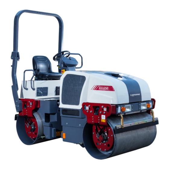
- Page 1 INSTRUCTION MANUAL Operating and Maintenance Vibratory rollers CC1250 Engine: Kubota D1703 Serial number: 10100379PHE004781- 4812106595_C - EN June-2018...
- Page 2 June 2018 Updated to new Dynapac standards Customer Acknowledgment • Dynapac reserves the right to make any changes or modifications without prior notice and without incurring any liability to retrofit machines previously shipped from the factory. • Dynapac will not be held responsible for any damages caused by unauthorized modification of the machine and its associated equipment.
-
Page 3: Table Of Contents
Table of Contents Section 1: Introduction 1.1 General Information ................... Instruction Manual Location ..................Receiving the Roller ....................Identification Data....................Roller Identification ....................Engine Identification ....................1.2 Roller Description ....................Identification of Major Components ................ Diesel Engine ......................Electrical System ....................Propulsion System/Transmission ................ - Page 4 Table of Contents Section 3: Special Instructions 3.1 Operational Limitations ..................Standard Lubricants and Other Recommended Oils and Fluids ......Higher Ambient Temperatures ................Lower Ambient Temperature - Freeze Risk ............Temperatures ....................... High Pressure Cleaning ..................Ambient Temperature Range................Operating Conditions For Stability ................
- Page 5 Table of Contents Hazard Warning Lights Switch................Rotating Beacon Switch(Optional) ................ Direction Indicator Switch ..................Parking Brake On/Off Switch ................Control Panel ....................... Control Panel Warnings Symbols .................. 28 Control Panel Notification Symbols ................29 Section 6: Inspections and Operations 6.1 General Information ..................
- Page 6 Table of Contents Before Driving ....................... 42 Securing for Loading ..................... 43 6.7 Special Conditions ................... Cold Weather Conditions ..................Hot Weather Conditions..................High Altitude Conditions ..................Long-term Parking ....................Section 7: Maintenance 7.1 General Information ..................7.2 Maintenance Schedule..................Maintenance Schedule Information ..............
-
Page 7: Section 1:Introduction
Perform the necessary pre-operational and post-operational checks on the roller. If any part of this manual cannot be understood, contact the supervisor or local Dynapac distributor. This is an essential condition for working safely with the CC 1250 roller. The correct CC 1250 operation, use, and regular maintenance are also essential elements to provide the highest performance and safety. -
Page 8: Instruction Manual Location
Figure 1-1: Instruction manual Location Provide the model type and serial number while contacting the local Dynapac service or parts office. Enter your roller data on the following lines to maintain roller and engine information necessary... -
Page 9: Roller Identification
Roller Identification The machine Product Identification Number (PIN) plate is located on left hand side of the rear frame. The PIN number is a 17 digit number which provides information about manufacturer, family model, check letter, no coding, production unit, and serial number. Figure 1-2: Location PIN Manufacturer Family/Model... -
Page 10: Engine Identification
Engine Identification Figure 1-4: Identification Plate Engine identification plate The engine identification number can be found on the top of the cylinder head cover. The engine identification plate provides model identification and other important data about the engine. Refer to the engine operation and maintenance manual for further information on the identification information. -
Page 11: Roller Description
1.2 Roller Description CC 1250 are two self-propelled vibratory tandem rollers in the three metric tonnes class featuring 1200 mm wide drums. The machines are equipped with drive, brakes, and vibration on both drums. To permit optimum performance on a wide range of applications and site requirements, the roller is equipped with: Diesel engine Electrical system... -
Page 12: Diesel Engine
Figure 1-6: Major Components Left Side Sprinkler system Engine Scrapper Throttle lever Propulsion motor Seat Water tank ROPS Air Cleaner Drum Propulsion Pump Steering joint Diesel Engine The machine is equipped with a water-cooled, straight three cylinder, and four-stroke diesel engine. Electrical System The machine has electronic control unit (ECU), relays, fuse, and switches. -
Page 13: Propulsion System/Transmission
Propulsion System/ Roller Applications Transmission The CC 1250 roller is built in accordance with international standards and recognized safety The propulsion system is a hydrostatic system rules. Nevertheless, misuse may constitute a risk with a hydraulic pump supplying two motors to the life and limb of the user or third parties, and connected in parallel. - Page 14 This page is intentionaly left blank...
-
Page 15: Section 2:Safety First
Section 2:Safety First 2.1 General Information This information is intended as a guide for trained and qualified personnel who are aware of the dangers involved in handling potentially hazardous equipment. It is not intended to contain a complete list of all safety precautions which should be observed by personnel using this equipment. -
Page 16: Warnings And Cautions
Do not make any unauthorized modifications to exchanged as a completed unit. Further this equipment. Dynapac cannot be held information can be found in the responsible for any accidents, incidents, or respective component descriptions and/ or damage to persons or property that are related to fitting and removal instructions. -
Page 17: Operating Safety
Operating Safety Driving Near Edges Know the working area. Familiarize with work site While driving near an edge make sure to maintain obstructions and any other potential hazards in 2/3 of the drum width on the solid ground. the area. N o t e The machine's center of gravity moves outwards when steering. -
Page 18: Gas Spring
Hydraulic Maintenance Always take into consideration that loose ground, steering the machine, vibration on, machine Safety speed across the ground and raising the center of gravity can cause the machine to topple at smaller The normal operating temperature of hydraulic oil slope angles than those specified here. -
Page 19: Transporting
Transporting • Use only appropriate means of transport and lifting gear of adequate capacity. • Fastening of loads and instructing the crane operators should be entrusted to the experienced persons only. The person giving the instructions must be within sight or sound of the operator. -
Page 20: Equipment Safety Decals
2.2 Equipment Safety Decals Before you operate, maintain, work around, or in any other way use this roller, read and understand the safety decals and safety labels located on the roller. Follow all directions on the labels. Do not remove or deface the labels. -
Page 21: Section 3:Special Instructions
Section 3:Special Instructions 3.1 Operational Limitations Standard Lubricants and Other Recommended Oils and Fluids Before leaving the factory, the systems and components are filled with the oils and fluids specified in the lubricant specification. These are suitable for ambient temperatures in the range -10°C to +40°C (5°F - 105°F). -
Page 22: High Pressure Cleaning
Stability Stability is affected by the orientation of the roller, surface stability (bearing strength), and wind conditions. Travel at a safe speed relevant to surrounding conditions. Contact the local Dynapac distributor, dealer, or service office for further information. Special Instructions... -
Page 23: Roll Over Protective Structure (Rops)
Roll Over Protective Jump Starting Structure (ROPS) Do not connect the negative cable to the negative terminal on the dead battery. A Operator life may be endangered if the spark can ignite the oxy-hydrogen gas following is not complied with. Do not add formed around the battery. - Page 24 This page is intentionaly left blank...
-
Page 25: Section 4: Specifications
Section 4: Specifications 4.1 Weight and Dimensions Figure 4-1:Dimensions, Side View Table 4-1:Weight and Dimensions Side View Wheel base 1811 mm (71.3 in) Length 2588 mm (101.89 in) Height, with ROPS 2649 mm (104.3 in) Height, without ROPS 1836 mm (72.3 in) Thickness 13 mm (0.5 in) Weight Standard equipped roller... -
Page 26: Diesel Engine
Figure 4-2:Dimensions Top View Table 4-2:Weight and Dimensions Top View Machine width with ROPS 1447 mm (57 in) Machine width without ROPS 1262 mm (49.7 in) Turning radius outer 4100 mm (149.6 in) Turning radius inner 2900 mm (114.2 in) Drum width 1200 mm (47.2 in) Diesel Engine... -
Page 27: Fluid Volume
Fluid Volume Table 4-4:Fluid Volumes Fuel tank 50 L (13.2 gal) Water tank 160 L (42.2 gal) Hydraulic tank 45 L (11.9 gal) Drum 7 L (1.3 gal) Coolant 5.5 L (1.4 gallons) Antifreez + 5.5 L (1.4 gallons) Water Working Capacity Table 4-5:Working Capacity Static linear load front... - Page 28 This page is intentionaly left blank...
-
Page 29: Section 5: Operation Controls
Section 5: Operation Controls 5.1 Instruments and Controls The instruments and controls section of this manual provides basic information about the operating controls, instruments, and indicators located on the consoles and around the roller. All the operation control from the operator console located in front of operator seat under steering wheel. -
Page 30: Starter Switch
Starter Switch Throttle Lever The starter switch starts and stops the engine. The throttle control regulates the speed of the There are three positions in the starter switch, engine. In forward position, the engine idles and in they are: the backward position, the engine runs with a full speed. -
Page 31: Emergency Stop
Emergency Stop Sprinkler Switch The emergency button is used to stop the engine Figure 5-7:Sprinkler Switch1 in an emergency situation which it cannot be shut off in an usual manner. It switches off the engine and activates the brakes. The emergency stop Upper position aborts the entire control operation in a quicker Intermediate position... -
Page 32: Horn Button
Horn Button Vibration Selector Switch The horn button is located on the switch In the upper position the vibration is switched off assembly. on the front drum and in the lower position the vibration is switched on in both the drums. Press the button to activate the horn. -
Page 33: Working Lights Switch(Optional)
Working Lights Depress the switch to switch on the rotating Switch(Optional) beacon. Depress the switch to switch on the working lights. Figure 5-15: Rotating Beacon Switch Figure 5-13: Working Lights Direction Indicator Switch Hazard Warning Lights The direction indicators are blinking lamps Switch mounted near the left and right, front and rear corners of the roller. -
Page 34: Control Panel
Control Panel Figure 5-18: Control Panel Battery/charging Fuel level Low fuel level Parking brake lamp Engine water temperature Glow plug Oil pressure, engine Hourmeter Control Panel Warnings Symbols Warning lights comes on when the starter switch is turned to the on position and should goes off once the engine has started. -
Page 35: Control Panel Notification Symbols
Control Panel Notification Symbols Notifications are displayed when the starter switch is turned to the on position and notifies that corresponding systems are operating. Table 5-2:Notification Lights Designation Function Description Parking brake indicator lamp The light illuminates when the parking brake is activated. - Page 36 This page is intentionaly left blank...
-
Page 37: Section 6:Inspections And Operations
Section 6:Inspections and Operations 6.1 General Information N o t e If you are not experienced with the roller controls read and understand section 5 - Operation Controls. The following operational hints should be observed: • Do not speed the engine when it is cold. •... -
Page 38: Check Engine Oil Level
Check Engine Oil Level Check Engine Coolant Level • Hot oil and hot components can cause Check the coolant level in sight glasess of the personal injury. Do not allow hot oil or expansion tank. Fill the cooling system when hot components to contact the skin. -
Page 39: Check The Fuel Level
Check the Fuel Level Check Batteries Fuel is flammable and may cause serious Batteries contain an acid and can cause injury or death. Shut off the engine, injury. Battery fumes can ignite and extinguish all open flames, and do not explode. -
Page 40: Before Starting The Engine
6.2 Before Starting the If any controls, instruments, or devices do Engine not function correctly report the defects to the proper personnel. Defects must be corrected before starting and operating Remember to carry out daily maintenance before the roller. starting the engine. Refer to section 7 - Seat(Standard) Adjustment Maintenance. -
Page 41: Check The Instruments And Lamps
Check the Instruments and Lamps Note Make sure that the emergency stop is pulled out and the parking brake is activated. If the forward/reverse lever is in neutral, the automatic brake function is engaged. 1. Turn the switch to on position. 2. -
Page 42: Operating The Roller
6.3 Operating the Roller 6. Make sure the throttle control is turned to low position. Operation Figure 6-6:Throttle control 1. Before the roller startup, a pre-operational general inspection of the roller must be performed in accordance with those instructions previously mentioned and in the instructions found in section 7 - Maintenance. -
Page 43: Vibration On One Drum
N o t e 3. In the lower position the vibration is activated As a general rule, do not operate the starter motor more than 30 seconds at a on both drums. time without pausing to allow the 4. In the upper position the vibration on the front starter motor to cool for at least 2 drum is switched off. -
Page 44: Switching Off
Switching Off 1. Press the vibration control button to off position. 2. Set the forward/reverse control to the neutral position. 3. Turn the throttle control to forward position and allow the engine to idle for a few minutes to cool. 4. -
Page 45: Lifting And Handling
6.4 Lifting and Handling Lifting the Roller • Use a crane/forklift to lift the equipment. Locking the Articulation • Pay attention when lifting and balancing the Note Lock the steering joint, before lifting the equipment. roller. • Seek a person to guide the way when lifting 1. -
Page 46: Towing The Roller
6.5 Towing the Roller Towing The roller can be moved up to 300 meters Towing Information (1,000 ft) using the instructions below. Proper equipment must be used to prevent N o t e Chock the drum to prevent the roller damage to the vehicle and the roller during any from moving when the brakes are tow. - Page 47 3. Tighten the nut against the brake tool until it Engaging the Brakes stops, indicating that the brakes is now 1. Screw out the nut again after towing. disengaged. 2. Screw off the brake tool and fit it back into its fixing holes Figure 6-11: Left Side of Drum 3.
-
Page 48: Transporting The Roller
6.6 Transporting the Start Up Roller 1. Before starting the engine, check inside, outside, and underneath the roller for people or obstructions. Transportation Procedures 2. Always horn before starting the roller to alert Safety Precautions everyone in the area. Before moving the roller on public roads, check for 3. -
Page 49: Securing For Loading
Securing for Loading Figure 6-14:Securing for Loading Double lashings, i.e. one lashing with two parts secured to two different lashing mounts. symmetrically located on the right and left sides. rubber Table 6-1:Lashings' Permitted Distance The lashings' permitted distance interval in meters (1 - 4: Double lashings, LC at least 1.7 tonnes (1700 daN), STF 300 kg (300daN)) Double L Double L... -
Page 50: Special Conditions
6.7 Special Conditions • Lubricate the steering joint bearings and both bearings on the steering cylinder with grease. Grease the steering cylinder piston Cold Weather Conditions with conservation grease. Grease the hinges on the doors to the engine compartment and •... -
Page 51: Section 7:Maintenance
Section 7:Maintenance 7.1 General Information Safety should be the main concern for anyone working on or around the roller. Do not perform any function that could put someone in danger. Always wear proper safety gear while working on or around the roller. This includes an approved hard hat, safety glasses, steel toe shoes, gloves, respirator, and ear protection. -
Page 52: Maintenance Schedule
7.2 Maintenance Schedule Maintenance Schedule Information The maintenance schedule shows those items requiring regular service and the interval at which they are performed. A regular service program is geared to the items listed under each interval. These intervals are based on average operating conditions. Before each consecutive interval is performed, all of the maintenance requirements from the previous interval must also be performed. - Page 53 Table 7-4: Maintenance at 200 Hours/600 Hours/Three Months Description Action Lubrication Engine Oil filter element Change Engine Oil Change Fuel filter element Change ROC cleaning Clean Fuel pipe and clamps Check Intake air line Check Battery Check Drum oil Check Table 7-5: Maintenance at 400 Hours/800 Hours/Six Months Description Action...
- Page 54 Description Action Lubrication ROC cleaning Clean Fuel pipe and clamps Check See engine manual Intake air line Check Valve clearance Check See engine manual Hydraulic oil filter Change Drum oil Change Table 7-7: Maintenance at 2,000 Hours/Two Years Description Action Lubrication Engine oil filter element Change...
-
Page 55: Refill Capacities/Lubricants
Spot check the several capscrews and the nuts for proper torque. If any are found loose, a more thorough investigation must be made. • If a defect is detected, that requires special service, stop the roller operation until the defect has been corrected. If necessary, contact the Dynapac representative for assistance. Maintenance... -
Page 56: Lubrication Chart
Periodic lubrication requirements are listed in the following Lubrication Chart. These requirements include lubricant checks and greasing designated areas of the roller. Description Part Number Remarks Quantity Engine oil 4812161855 Dynapac engine oil 50 5 L (1.3 gallons) Hydraulic oil 4812161868 Dynapac hydraulic 300 20 L (5.3 gallons) Drum oil 4812161887 Dynapac Drum oil 1000 5L (1.3 gallons) - Page 57 Table 7-10: Maintenance Symbols Symbol Description Symbol Description Engine oil level Air filter Engine oil filter Battery Hydraulic reservoir level Sprinkler Hydraulic fluid filter Sprinkler water Drum oil level Recycling Lubrication oil Fuel filter Maintenance...
-
Page 58: Standard Torque Values
7.4 Standard Torque Values Use only the proper tools (inches) on hardware. Other tools may not fit properly and may slip and cause injury. Head Markings Fasteners should be replaced with the same grade or a higher grade. If higher grade fasteners are used, these should only be tightened to the strength of the original grade fastener. - Page 59 Table 7-11: Recommended Torques in ft·lb Metric coarse screw thread, bright galvanized (fzb): M-thread 12.9, Size 8.8 Oiled 8.8 Dry 10.9 Oiled 10.9, Dry 12.9, Dry Oiled 1080 1130 1260 1580 1770 1900 2100 Table 7-12: Recommended Torques in N·m Metric coarse thread, zinc-treated (Dacromet/GEOMET) M-thread Size...
-
Page 60: Maintenance As Required
7.5 Maintenance as Required Service as Required The preventive maintenance and service in this section requires attention on the need basis, before, during, and after the operation shift. This is in addition to the 8 to 10 hour daily routine maintenance procedures. -
Page 61: Air Cleaners
Air Cleaners Air Cleaner Pre-Cleaner Wipe clean the inside of the cover and the filter The following are detailed instructions for housing. Wipe also both surfaces for the outlet performing routine maintenance procedures on pipe. the air cleaner. Not e Check that the hose clamps between the Raw, unfiltered air can damage the filter housing and the suction hose are... -
Page 62: Air Cleaner Main Filter
Air Cleaner Main Filter 5. Make sure the main filter washer are not cracked or damaged. Replace if necessary. The air cleaner is the dry type with two elements; 6. The backup filter should be replaced if the air a main filter that is replaceable and can be cleaner visual restriction indicator is red after cleaned, and a backup filter that should only be servicing the main filter. -
Page 63: Hose And Clamps
Engine Air Circulation Check that the engine has free circulation of Refer to the engine service and maintenance cooling air through the grille in the engine manuals for specific information on the engine maintenance. compartment. Not e Switch off the engine before filling the oil. Figure 7-4: Air Circulation N o t e Care must be taken while draining the... -
Page 64: Batteries
Batteries 4. Remove and replace the oil filter. The following battery maintenance must be Figure 7-5: Fuel Filters carried out as part of the 200 hour routine maintenance schedule. Batteries contain an acid and can cause injury. Skin and eye contact with battery fluid can cause injury. -
Page 65: Check Electrolyte Level
Fuel Tank Check Electrolyte Level 1. Shut off the engine. Refuel every day before starting to work. 2. Lockout/tagout the roller as per the site 1. Screw off the lockable tank cap. specific procedure. 2. Fill diesel fuel to the lower edge of the fil- 3. -
Page 66: Lowering Of Engine Hood
Lowering of Engine Hood Coolant System 1. Stand on the left side of the engine hood. Check that all hoses/hose connectors are intact and tight. Fill with coolant as specified in the 2. Press in the black rod and carefully lower the lubricants specification. -
Page 67: Water Tank
Water Tank 3. Adjust the contact surface on both scraper attachments. Unscrew the tank cap and fill with clean water. Do 4. Tighten all the screws after adjustment. not remove the strainer. See technical specifications for the tank volume. Figure 7-11: Drum N o t e A small amount of environment- friendly antifreeze is added. -
Page 68: Sprinkler System
Sprinkler System Start the sprinkler system and make sure that nonozzles are clogged. If necessary, clean clogged nozzles and the coarse filter located by the water pump. The sprinkler system should be drained if there is a risk of freezing. Wear protective eye glases when working with compressed air. -
Page 69: Lubrication And Filters
7.6 Lubrication and Checking Hydraulic Oil Level Filters If the hydraulic oil level is low, add hydraulic oil. 1. Level the roller. Hydraulic Reservoir 2. Check the reservoir oil level by viewing the sight gauge. Verify that fluid level is near the The hydraulic reservoir oil level must be checked maximum level indicated on the sight glass. - Page 70 Steering Cylinder and Steering Drum - Oil Level Joint 1. Run the roller slowly until the oil plug is opposite one of the inspection holes. The steering cylinder is located under the operator’s platform. There is a grease fitting near 2.
- Page 71 Housekeeping The complete roller must be given a weekly cleaning. Daily cleaning will be required if material is adhering to the roller working parts. 1. Make sure the operator areas, steps, and grab rails are clean. Oil, grease, snow, ice, or mud in these areas can be slippery.
- Page 72 This page is intentionaly left blank...
- Page 74 Plot no 01, Gat no. 163-168, Alandi Markal road, Village: Fulgaon, Taluka: Haveli, Dist: Pune- 412216, India...
Need help?
Do you have a question about the CC1250 and is the answer not in the manual?
Questions and answers