Table of Contents
Advertisement
Quick Links
Instruction manual
Instruction manual
Operating & Maintenance
Operating & Maintenance
4812158801_E.pdf
4812158801_E.pdf
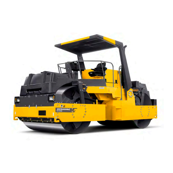
Vibratory roller
Vibratory roller
CC722/7200
CC722/7200
Cummins QSB 6.7 C (IIIB/T4i)
Cummins QSB 6.7 C (IIIB/T4i)
Serial number
Serial number
10000326xxA007761 -
10000326xxA007761 -
10000361xxA014104 -
10000361xxA014104 -
Translation of original instruction
Translation of original instruction
Reservation for changes
Reservation for changes
Printed in Sweden
Printed in Sweden
Engine
Engine
Advertisement
Table of Contents


Need help?
Do you have a question about the CC722 and is the answer not in the manual?
Questions and answers