Table of Contents
Advertisement
Quick Links
Instruction manual
Instruction manual
Operating & Maintenance
Operating & Maintenance
4812164901_A.pdf
4812164901_A.pdf
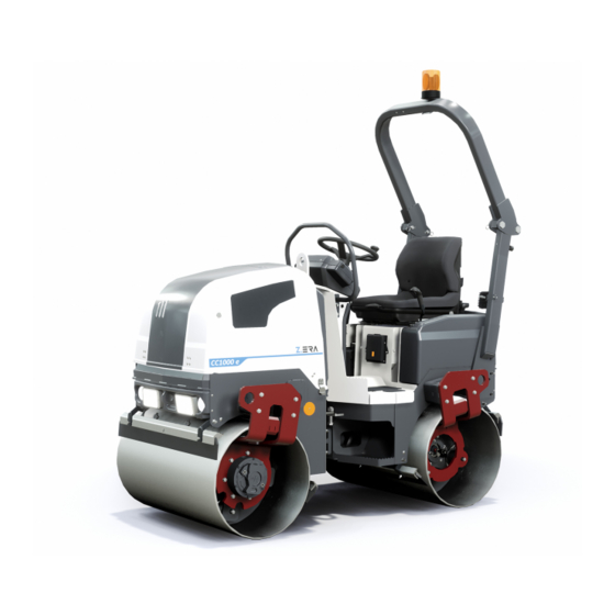
Vibratory roller
Vibratory roller
Electric powered
Electric powered
Serial number
Serial number
10000615xxA034264 -
10000615xxA034264 -
10000618xxA034278 -
10000618xxA034278 -
Translation of original instruction
Translation of original instruction
Reservation for changes
Reservation for changes
Printed in Sweden
Printed in Sweden
CC900 e
CC900 e
CC1000 e
CC1000 e
Advertisement
Table of Contents


Need help?
Do you have a question about the CC900 e and is the answer not in the manual?
Questions and answers