Table of Contents
Advertisement
Quick Links
Instruction manual
Instruction manual
Operating & Maintenance
Operating & Maintenance
4812164101_A.pdf
4812164101_A.pdf
Vibratory roller
Vibratory roller
Kubota D722-E4B
Kubota D722-E4B
Serial number
Serial number
10000381xxA023805 -
10000381xxA023805 -
Translation of original instruction
Translation of original instruction
Reservation for changes
Reservation for changes
Printed in Sweden
Printed in Sweden
CC950
CC950
Engine
Engine
Advertisement
Table of Contents

Related Manuals for Dynapac CC950


Summary of Contents for Dynapac CC950
- Page 1 Instruction manual Instruction manual Operating & Maintenance Operating & Maintenance 4812164101_A.pdf 4812164101_A.pdf Vibratory roller Vibratory roller CC950 CC950 Engine Engine Kubota D722-E4B Kubota D722-E4B Serial number Serial number 10000381xxA023805 - 10000381xxA023805 - Translation of original instruction Translation of original instruction...
-
Page 3: Table Of Contents
Table of Contents Introduction ..........................1 Signal symbols and meaning ..............1 The machine ....................1 Intended use ....................1 Safety information ..................1 General ....................... 2 Signal symbols and meaning ..............3 Safety - General instructions....................5 Safety - when operating ......................7 Seated position ................... - Page 4 Weights and volumes................18 Working capacity..................18 General ..................... 18 Tightening torque ..................19 ROPS - bolts ..................... 20 Hydraulic system..................20 Machine description ....................... 21 Diesel engine .................... 21 Electrical system ..................21 Propulsion system/Transmission .............. 21 Brake system .................... 21 Steering system ..................
- Page 5 Battery isolation switch - On..............37 Operator’s seat - Adjusting............... 37 Instruments and lamps - Checking............38 Sprinkler - Check..................39 On machine with pressurized sprinkler system: ......39 Parking brake .................... 40 Emergency stop ..................40 Interlock..................... 41 Operator position..................42 View ......................
- Page 6 Lifting the roller..................53 Unlocking the articulation ................53 Transport ......................... 54 Securing CC950 for loading ..............55 Securing CC950 for loading (Side along the trailer)..........57 Retractable ROPS (Optional)..............59 Towing/Recovering....................59 Towing the roller..................60 Releasing the brake .................. 61 Operating instructions - Summary ..................
- Page 7 Every 400 / 800 / 1200 / 1600 hours of operation ........74 Every 1000 hours of operation ..............75 Every 2000 hours of operation ..............76 Service - Checklist....................77 Maintenance, 10h ........................79 Diesel engine Check oil level ..............79 Hydraulic reservoir cap - Check ..............
- Page 8 Rubber elements and fastening screws - Check........95 Fan belt tension - Check ................95 Water seperator - Drain................96 Belt tension on the hydraulic vibration and steering pump drive belt - Check ......................96 Drum bearing seat - Check and lubrication..........96 Maintenance - 200 / 600 / 1400 / 1800 h ................
- Page 9 Outside / Inside radiator core - Clean ............. 112 Fan belt - Change ................... 113 Engine oil and oil filter - Change ............. 114 Engine valve clearance - Check.............. 115 Cooling freezing point - Check ..............115 Air cleaner filter element - Change............116 Hydraulic reservoir cap - Check ..............
- Page 10 Front drum - Changing the oil ..............130 Forward / Reverse controls and joints - Check and lubrication ................131 Belt tension on the hydraulic vibration and steering pump drive belt - Check ...................... 132 4812164101_A.pdf 2022-02-09...
-
Page 11: Introduction
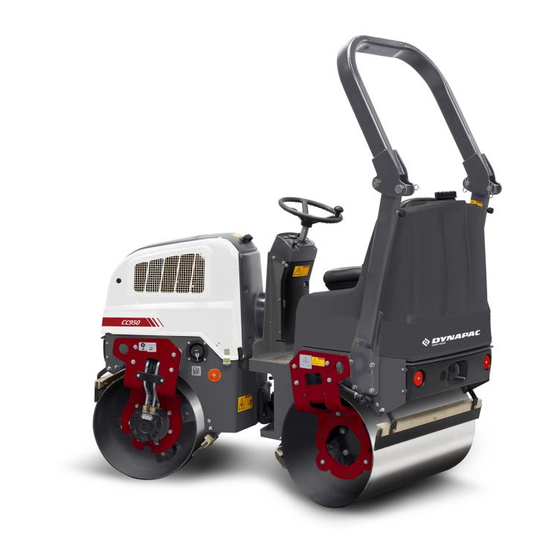
Introduction Signal symbols and meaning The machine Dynapac CC950 is a vibratory tandem roller in the 1,5 metric tonnes class featuring 900 mm wide drums. The machine is equipped with drive and brakes on both drums, and vibration on front drum. -
Page 12: General
Introduction Replace immediately the instruction manuals if Replace immediately the instruction manuals if lost, damaged or unreadable. lost, damaged or unreadable. Ensure good ventilation (extraction of air by fan) Ensure good ventilation (extraction of air by fan) where the engine is run indoors. where the engine is run indoors. -
Page 13: Signal Symbols And Meaning
10 and 50 hours of operation can be performed by the machine operator. Other maintenance intervals must be carried out by accredited (Dynapac) service personnel. Additional instructions for the engine can be Additional instructions for the engine can be found in the manufactuer's engine manual. - Page 14 Introduction 4812164101_A.pdf 2022-02-09...
-
Page 15: Safety - General Instructions
Never jump down from the machine. • • Dynapac always recommends mounted ROPS (Roll Over Protective Dynapac always recommends mounted ROPS (Roll Over Protective Structure), or a ROPS-approved cab and seat belt usage. Structure), or a ROPS-approved cab and seat belt usage. - Page 16 Modifications to the roller, including the use of any attachment/equipment, Modifications to the roller, including the use of any attachment/equipment, not approved by Dynapac that might compromise safety (including visibility) not approved by Dynapac that might compromise safety (including visibility) are not allowed.
-
Page 17: Safety - When Operating
ROPS are operated when machines with foldable ROPS are operated 2. Seat belt Work driving Dynapac always recommends mounted ROPS Dynapac always recommends mounted ROPS (Roll Over Protective Structure) and seat belt (Roll Over Protective Structure) and seat belt usage. -
Page 18: Driving Near Edges
Safety - when operating when compacting close to edges and holes. Do not compact with a large overlap from the previous track in order to maintain roller stability. Consider other compaction methods such as remote-control or a walk-behind roller close to steep slopes or where the bearing strength of the substrate is unknown. - Page 19 Safety - when operating Prevent persons from entering or remaining in Prevent persons from entering or remaining in the risk zone, i.e. a distance of at least 7 m (23 the risk zone, i.e. a distance of at least 7 m (23 ft) in all directions from operating machines.
- Page 20 Safety - when operating 4812164101_A.pdf 2022-02-09...
-
Page 21: Special Instructions
Special instructions Special instructions Standard lubricants and other recommended oils and fluids Before leaving the factory, the systems and components are filled with the oils and fluids specified in the lubricant specification. These are suitable for ambient temperatures in the range -15°C to +40°C (5°F - 105°F). -
Page 22: High Pressure Cleaning
Special instructions High pressure cleaning Do not spray water directly onto electrical components or the instrument panels. Place a plastic bag over the fuel filler cap and secure with a rubber band. This is to avoid high pressure water entering the vent hole in the filler cap. This could cause malfunctions, such as the blocking of filters. -
Page 23: Battery Handling
Special instructions Never repair a damaged ROPS structure, it must Never repair a damaged ROPS structure, it must be replaced with a new one. be replaced with a new one. Battery handling When removing batteries, always disconnect the When removing batteries, always disconnect the negative cable first. - Page 24 Special instructions 4812164101_A.pdf 2022-02-09...
-
Page 25: Technical Specifications
Technical specifications Technical specifications Vibrations - Operator station (ISO 2631) The vibration levels are measured in accordance with the operational cycle described in The vibration levels are measured in accordance with the operational cycle described in EU directive 2000/14/EC on machines equipped for the EU market, with vibration switched EU directive 2000/14/EC on machines equipped for the EU market, with vibration switched on, on soft polymer material and with the operator’s seat in the transport position. -
Page 26: Dimensions, Side View
Technical specifications Dimensions, side view Dimensions Dimensions Wheelbase Wheelbase 1350 1350 53,1 53,1 Drum diameter Drum diameter 23,0 23,0 Height, with ROPS Height, with ROPS 2300 2300 90,5 90,5 Height, w/o ROPS Height, w/o ROPS 1585 1585 62,4 62,4 Ground clearance Ground clearance 10,3 10,3... -
Page 27: Dimensions, Top View
Technical specifications Dimensions, top view Dimensions Dimensions Width Width 38,2 38,2 Overhang Overhang 1,38 1,38 Turning radius, outside Turning radius, outside 2700 2700 106,3 106,3 Turning radius, inside Turning radius, inside 2660 2660 104,7 104,7 Drum shell thickness Drum shell thickness 35,4 35,4 α... -
Page 28: Weights And Volumes
Technical specifications Weights and volumes Weights Weights Operating mass (EN500) Operating mass (EN500) 1340 kg 1340 kg 2955 lbs 2955 lbs Fluid volumes Fluid volumes Fuel tank Fuel tank 23 liters 23 liters 6,0 gal 6,0 gal Water tank Water tank 175 liters 175 liters 46,2 gal... -
Page 29: Tightening Torque
Technical specifications Tightening torque Tightening torque in Nm for oiled or dry bolts tightened with a torque wrench. Metric coarse screw thread, bright galvanized (fzb): STRENGTH CLASS: 8.8, Oiled 8.8, Oiled 8.8, Dry 8.8, Dry 10.9, Oiled 10.9, Oiled 10.9, Dry 10.9, Dry 12.9, Oiled 12.9, Oiled... -
Page 30: Rops - Bolts
Technical specifications ROPS - bolts Bolt dimensions : Bolt dimensions : M12 (PN 4700508063) M12 (PN 4700508063) Strength class : Strength class : Tightening torque : Tightening torque : 70 Nm 70 Nm ROPS-bolts which are to be torque tightened ROPS-bolts which are to be torque tightened must be dry. -
Page 31: Machine Description
Machine description Machine description Diesel engine The machine is equipped with an liquid-cooled, three cylindre, diesel engine. Electrical system The electrical system on the machine is controlled by relay logic. It's operated by buttons and switches. Propulsion system/Transmission The propulsion system is a hydrostatic system with a hydraulic pump supplying two motors connected in serial. -
Page 32: Identification
ROPS structure must be replaced immediately. Never perform unauthorized modifications on the ROPS structure without first having discussed the modification with Dynapac's production unit. Dynapac determines whether the modification could result in the approval according to the ROPS standards becoming invalid. -
Page 33: Machine Plate
Machine description Machine plate The machine plate (1) is attached to the front right side of the rear frame, beside the steering joint. The plate specifies the manufacturers name and address, the type of machine, the PIN, Product Identification Number (serial number), operating weight, engine power and year of manufacture. -
Page 34: Engine Plates
Machine description Engine plates The engine serial number (1) is punched below the starter. Please specify the engine serial number when ordering spares. Refer also to the engine manual. Fig. Engine 1. Serial number 4812164101_A.pdf 2022-02-09... -
Page 35: Decals
Machine description Decals Location - decals Fig. Location, decals and signs Securing point Securing point 4700382751 4700382751 Hoisting plate Hoisting plate 4700904870 4700904870 Lifting point Lifting point 4700357587 4700357587 Warning - Locking Warning - Locking 4812125363 4812125363 Warning, Instruction manual Warning, Instruction manual 4700903459 4700903459... -
Page 36: Location - Decals, California
Machine description Location - decals, CALIFORNIA Proposition 65 Warning, CALIFORNIA Warning, CALIFORNIA 4812130471 4812130471 Proposition 65 Proposition 65 Fig. Location Safety decals Always make sure that all safety decals are completely legible, and remove dirt or order new decals if they have become illegible. - Page 37 Machine description 4700903459 Warning - Instruction manual The operator must read the safety, operation and maintenance instructions before operating the machine. 4700908229 Warning - Risk of crushing The articulation must be locked when lifting. Read the instruction manual. 4811000351 Warning - Risk of tip over If ROPS (Roll Over Protective Structure) is fitted to the roller, always wear the seat belt.
- Page 38 Machine description 4812130471 Warning CALIFORNIA - Proposition 65 4812164101_A.pdf 2022-02-09...
-
Page 39: Info Decals
Machine description Info decals 1. Securing point 1. Securing point 2. Lifting point 2. Lifting point 6. Battery disconnector 6. Battery disconnector 4700382751 4700382751 4700357587 4700357587 4700904835 4700904835 7. Handbook compartment 7. Handbook compartment 9. Hoisting plate 9. Hoisting plate 12. -
Page 40: Locations - Control Panel And Controls
Machine description Locations - Control panel and controls Fig. Control panel on machine with Fig. Control panel on machine with non-pressurized sprinkler system pressurized sprinkler system Fuse box Fuse box Horn Horn Parking brake Parking brake Emergency stop Emergency stop (Not in use) (Not in use) Starter switch... - Page 41 Machine description Locations - Control panel and controls Fig. Operator position Fig. Control panel Seat switch Seat switch Fuel level Fuel level Forward/reverse lever Forward/reverse lever Parking brake lamp Parking brake lamp Vibration On/Off Vibration On/Off Glow plug Glow plug Handbook compartment Handbook compartment Hourmeter...
-
Page 42: Function Description
Machine description Function description Designation Designation Symbol Symbol Function Function Fuse box (on control column) Fuse box (on control column) Contains fuses for the electrical system. See under Contains fuses for the electrical system. See under the heading ‘Electrical system’ for a description of the heading ‘Electrical system’... - Page 43 Machine description Designation Designation Symbol Symbol Function Function Fuel level Fuel level Shows the fuel level. Shows the fuel level. Parking brake warning lamp, Parking brake warning lamp, The light comes on when the Parking brake is The light comes on when the Parking brake is Hydraulic oil temperature Hydraulic oil temperature activated.
-
Page 44: Electrical System
Machine description Electrical system Relays and fuses on the machine The figure shows the positions of the various fuses and relays. The table below gives their amperage and function. All fuses are flat pin fuses. Relays Relays Starting Starting Start, vibration, brake Start, vibration, brake Brake lamp Brake lamp... - Page 45 Machine description Relays and fuses on the machine The figure shows the positions of the various fuses and relays. The table below gives their amperage and function. All fuses are flat pin fuses. Relays Relays Start, Vibration, Brake Start, Vibration, Brake Drive restriction relay Drive restriction relay Cooling fan, hydraulic system (Option)
- Page 46 Machine description 4812164101_A.pdf 2022-02-09...
-
Page 47: Operation
Operation Operation Before starting Battery isolation switch - On Remember to carry out daily maintenance. Refer to the maintenance instructions. The battery disconnector is located on the left side of the engine compartment. Turn the key (1) to the On position. The roller is now supplied with power. -
Page 48: Instruments And Lamps - Checking
Operation Instruments and lamps - Checking Make sure that the emegency stop is pulled out Make sure that the emegency stop is pulled out and the parking brake is activated. When the and the parking brake is activated. When the forward/reverse lever is in neutral, the automatic forward/reverse lever is in neutral, the automatic brake function is engaged. -
Page 49: Sprinkler - Check
Operation Sprinkler - Check Make sure that the parking brake (2) is activated. Make sure that the parking brake (2) is activated. Set the knob (5) for the sprinkler in the open position and check that the drums are watered. Fig. -
Page 50: Parking Brake
Operation Parking brake Activate the parking brake (2) Activate the parking brake (2) before leaving the machine. before leaving the machine. The machine can be started with the parking brake (2) deactivated. Emergency stop The machine can only be started if the emergency stop (7) is deactivated. -
Page 51: Interlock
Operation Interlock The roller is equipped with Interlock. The diesel engine with switch off after 4 seconds if the operator gets off the seat when going forwards/backwards. If the control is in neutral when the operator stands up a buzzer will go on until the parking brake button is activated. -
Page 52: Operator Position
Operation Operator position Replace the seat belt (1) if it shows signs of Replace the seat belt (1) if it shows signs of wear or has been subjected to high levels of wear or has been subjected to high levels of force. -
Page 53: View
Operation If ROPS (Roll Over Protective Structure) is fitted to the roller, always wear the seat belt (1) provided and wear a protective helmet. View Before starting, make sure that the view forwards and backwards is unobstructed. Fig. View 2022-02-09 4812164101_A.pdf... -
Page 54: Starting
Operation Starting Starting the engine Make sure that the parking brake (2) is activated. Sit down in the operator's seat and set the forward/reverse lever (12) in neutral. You cannot start the gasoline engine with the lever in any other position. Set the RPM control (16) to idle. -
Page 55: Driving
Operation Driving Operating the roller Under no circumstances is the machine to be Under no circumstances is the machine to be operated from the ground. The operator must be operated from the ground. The operator must be seated at the machine during all operation. seated at the machine during all operation. -
Page 56: Interlock/Emergency Stop/Parking Brake - Check
Operation Interlock/Emergency stop/Parking brake - Check The interlock, emergency stop and parking brake must The interlock, emergency stop and parking brake must be checked daily before operating. A function check of be checked daily before operating. A function check of the interlock and emergency stop requires a restart. -
Page 57: Braking
Operation Braking Service brake When starting and driving a machine that is cold, When starting and driving a machine that is cold, remember that the hydraulic fluid is also cold and remember that the hydraulic fluid is also cold and that braking distances can be longer than normal that braking distances can be longer than normal until the machine reaches the working temperature. -
Page 58: Emergency Stop
Operation Emergency stop The emergency stop is activated by pressing the button (7). Hold the steering wheel firmly and brace yourself for a sudden stop. The brake is applied and the engine stops. After an emergency stop, return the forward/reverse lever to neutral and deactivate the emergency stop by pulling out the button (7). -
Page 59: Parking
Operation Parking Chocking the drums Never leave the operator platform without Never leave the operator platform without activating the parking brake. activating the parking brake. Make sure that the roller is parked in a safe place Make sure that the roller is parked in a safe place with respect to other road users. - Page 60 Operation 4812164101_A.pdf 2022-02-09...
-
Page 61: Long-Term Parking
Long-term parking Long-term parking The following instructions should be followed The following instructions should be followed when long term parking (more than one month). when long term parking (more than one month). These measures apply when parking for a period of up to 6 months. -
Page 62: Hydraulic Reservoir
Long-term parking Hydraulic reservoir Fill the hydraulic reservoir to the uppermost level mark (see under the heading ‘Every 10 hours of operation.’) Steering cylinder, hinges, etc. Grease the steering cylinder piston with conservation grease. Grease the hinges on the doors to the engine compartment. -
Page 63: Miscellaneous
Miscellaneous Miscellaneous Locking the articulation Before lifting the roller the steering joint must be Before lifting the roller the steering joint must be locked to prevent it turning. locked to prevent it turning. Turn the steering wheel to the straight ahead position. Switch off the machine. -
Page 64: Transport
Miscellaneous Transport Tie-down and secure the machine according to the Cargo Securing Certificate for the specific machine if this is avaliable and applicable. If not, tie down and secure the machine according to the cargo securing rules that are valid for the country where the transport takes place. -
Page 65: Securing Cc950 For Loading
Miscellaneous Securing CC950 for loading Securing of a double vibratory roller of model CC950 from Dynapac loaded on a trailer for transport on road and in the Baltic / North sea (sea area A/B). Direct of travel 1 - 2 = double lashings, i.e. one lashing with two parts secured to two different lashing mounts on 1 - 2 = double lashings, i.e. - Page 66 Miscellaneous The contact surfaces must be clean, wet or dry, and free from frost, ice and snow. If there is a The contact surfaces must be clean, wet or dry, and free from frost, ice and snow. If there is a risk of frost, ice and/or snow the platform has to be salted.
-
Page 67: Securing
Miscellaneous Securing CC950 for loading (Side along the trailer) Securing of two CC950 vibratory rollers from Dynapac loaded side by side along a trailer for transport on road and in Baltic sea (Sea area A). Direct of travel 1 - 2 = double lashings, i.e. one lashing with two parts secured to two different lashing mounts on 1 - 2 = double lashings, i.e. - Page 68 Miscellaneous Load carrier Load carrier Ensure that: Ensure that: When loaded, the vibratory roller is centered laterally on the platform (± 5 cm). When loaded, the vibratory roller is centered laterally on the platform (± 5 cm). The parking brake is applied and in good working condition, and the articulated joint lock is The parking brake is applied and in good working condition, and the articulated joint lock is closed.
-
Page 69: Retractable Rops (Optional)
Miscellaneous Retractable ROPS (Optional) The machine can be equipped with retractable ROPS. Risk of crush injury when raising and lowering Risk of crush injury when raising and lowering ROPS. ROPS. If the roller is equipped with a retractable ROPS, If the roller is equipped with a retractable ROPS, the machine must only be operated when it is lifted the machine must only be operated when it is lifted up and locked. -
Page 70: Towing The Roller
Miscellaneous Towing the roller A towing bar must be used when towing, as the A towing bar must be used when towing, as the roller has no brakes and can only be slowed and roller has no brakes and can only be slowed and stopped by the vehicle towing the roller. -
Page 71: Releasing The Brake
Miscellaneous Switch off the diesel engine and Switch off the diesel engine and activate the parking brake. activate the parking brake. Chock the drum to prevent the roller Chock the drum to prevent the roller from moving when the brakes are disengaged. from moving when the brakes are disengaged. - Page 72 Miscellaneous 4812164101_A.pdf 2022-02-09...
-
Page 73: Operating Instructions - Summary
Operating instructions - Summary Operating instructions - Summary Follow the SAFETY INSTRUCTIONS specified in the Safety Manual. Follow the SAFETY INSTRUCTIONS specified in the Safety Manual. Make sure that all instructions in the MAINTENANCE section are followed. Make sure that all instructions in the MAINTENANCE section are followed. Set the Emergency stop to its pulled-out position. - Page 74 Operating instructions - Summary 4812164101_A.pdf 2022-02-09...
-
Page 75: Preventive Maintenance
Preventive maintenance Preventive maintenance Complete maintenance is necessary for the machine to function satisfactorily and at the lowest possible cost. The Maintenance section includes the periodic maintenance that must be carried out on the machine. The recommended maintenance intervals assume that the machine is used in a normal environment and working conditions. - Page 76 Preventive maintenance 4812164101_A.pdf 2022-02-09...
-
Page 77: Maintenance - Lubricants And Symbols
See the extremely low ambient temperatures. See the ‘Special instructions’ chapter, or consult ‘Special instructions’ chapter, or consult Dynapac. Dynapac. 2022-02-09 4812164101_A.pdf... - Page 78 P/N 4812161856 (20 liters) P/N 4812161856 (20 liters) HYDRAULIC FLUID HYDRAULIC FLUID Air temperature -15°C - +40°C Air temperature -15°C - +40°C Dynapac Hydraulic 300 P/N 4812161868 (20 liters) Dynapac Hydraulic 300 P/N 4812161868 (20 liters) (5°F-104°F) (5°F-104°F) P/N 4812161869 P/N 4812161869...
-
Page 79: Maintenance Symbols
Maintenance - Lubricants and symbols Maintenance symbols Engine, oil level Engine, oil level Air filter Air filter Engine, oil filter Engine, oil filter Battery Battery Hydraulic reservoir, level Hydraulic reservoir, level Sprinkler Sprinkler Hydraulic fluid, filter Hydraulic fluid, filter Sprinkler water Sprinkler water Drum, oil level Drum, oil level... - Page 80 Maintenance - Lubricants and symbols 4812164101_A.pdf 2022-02-09...
-
Page 81: Maintenance - Maintenance Schedule
Maintenance - Maintenance schedule Maintenance - Maintenance schedule Service and maintenance points 12, 13 Fig. Service and maintenance points 1. Water tank, filling 1. Water tank, filling Air cleaner Air cleaner Hydraulic fluid, filling Hydraulic fluid, filling 2. Forward/Reverse lever 2. -
Page 82: General
Maintenance - Maintenance schedule General Periodic maintenance should be carried out after the number of hours specified. Use the daily, weekly etc. periods where number of hours cannot be used. Remove all dirt before filling, when checking Remove all dirt before filling, when checking oils and fuel and when lubricating using oil or oils and fuel and when lubricating using oil or grease. -
Page 83: After The First 50 Hours Of Operation
Maintenance - Maintenance schedule After the FIRST 50 hours of operation Refer to the contents to find the page number of the sections referred to ! Action Action Comment Comment Change the engine oil Change the engine oil Refer to the engine manual Refer to the engine manual Change the engine oil filter Change the engine oil filter... -
Page 84: Every 200 / 600 / 1400 / 1800 Hours Of Operation
Maintenance - Maintenance schedule Every 200 / 600 / 1400 / 1800 hours of operation Refer to the contents to find the page number of the sections referred to ! Pos. Pos. Action Action Comment Comment in fig in fig Check lubrication of controls and pivots Check lubrication of controls and pivots Lubricate as necessary... -
Page 85: Every 1000 Hours Of Operation
Maintenance - Maintenance schedule Every 1000 hours of operation Refer to the contents to find the page number of the sections referred to ! Pos. Pos. Action Action Comment Comment in fig in fig Check lubrication of controls and pivots Check lubrication of controls and pivots Lubricate as necessary Lubricate as necessary... -
Page 86: Every 2000 Hours Of Operation
Maintenance - Maintenance schedule Every 2000 hours of operation Refer to the contents to find the page number of the sections referred to ! Pos. Pos. Action Action Comment Comment in fig in fig Drain and clean the water tank Drain and clean the water tank Clean the outside/inside of radiator core Clean the outside/inside of radiator core... -
Page 87: Service - Checklist
Maintenance - Maintenance schedule Service - Checklist 2022-02-09 4812164101_A.pdf... - Page 88 Maintenance - Maintenance schedule 4812164101_A.pdf 2022-02-09...
-
Page 89: Maintenance, 10H
Maintenance, 10h Maintenance, 10h Every 10 hours of operation (Daily) Park the roller on a level surface. Park the roller on a level surface. The engine must be switched off and the The engine must be switched off and the parking brake activated when checking or parking brake activated when checking or adjusting the roller, unless otherwise specified. -
Page 90: Hydraulic Reservoir Cap - Check
Maintenance, 10h Hydraulic reservoir cap - Check Unscrew and make sure that the reservoir cap is not blocked. Air must have unobstructed passage through the cap in both directions. If blocked in either direction, clean with a little diesel oil and blow with compressed air until unblocked or replace the cap with a new one. -
Page 91: Water Tank - Filling
Maintenance, 10h Water tank - Filling Unscrew the tank cap (1), and fill with clean Unscrew the tank cap (1), and fill with clean water. water. Fill the water tank; it holds 175 liters. Only additive: A small amount of environmentally Only additive: A small amount of environmentally friendly antifreeze. -
Page 92: Sprinkler System - Check, Cleaning
Maintenance, 10h Sprinkler system - Check, cleaning Check that the holes in the sprinkler pipe (1) are not clogged, clean if necessary. Fig. Sprinkler system 1. Sprinkler pipes with holes for water. On machine with pressurized sprinkler system: Check that the holes in the sprinkler nozzles (1) are not blocked. -
Page 93: Sprinkler System/Drum Cleaning Of Sprinkler Nozzle
Maintenance, 10h Sprinkler system/Drum Cleaning of sprinkler nozzle Dismantle the blocked nozzle by hand. Blow the nozzle (1) and fine filter (3) clean using compressed air. Alternatively, fit replacement parts and clean the blocked parts later on. Nozzle Nozzle Colour Colour l/min (at 2.0 l/min (at 2.0... -
Page 94: Air Cleaner - Check
Maintenance, 10h Air cleaner - check As the element of the air cleaner employed on this engine is a dry type, never apply oil to it. Open the evacuator valve once a week under ordinary conditions - or daily when used in a dusty place - to get rid of large particles of dust and dirt. -
Page 95: Coolant, Level Check - Filling
Maintenance, 10h Coolant, Level check - filling Place the roller on a level surface. Stand firmly with both feet on a non-slip surface. Check that all hoses/hose connectors are intact and tight. Check that the coolant level is between max./min. in the sight glass (2). -
Page 96: Refueling
Maintenance, 10h Refueling Refuel the tank every day before starting work. Open the tank cap and fill through the filler pipe (1). Never refuel while the engine is running. Do not Never refuel while the engine is running. Do not smoke and avoid spilling fuel. -
Page 97: Scrapers, Fixed Checking - Setting
Maintenance, 10h Scrapers, fixed Checking - Setting Make sure that the scrapers are undamaged. Adjust the scrapers so that they are 1-2 mm from the drum. For special asphalt compounds, it may be better if the scraper blades (1) lie lightly against the drums. Asphalt remnants can accumulate on the scraper and affect the contact force. -
Page 98: Brakes - Check
Maintenance, 10h Brakes - Check Check operation of the brakes as follows: Check operation of the brakes as follows: Checking the parking brake Drive the roller slowly forward. Hold the steering wheel firmly and brace yourself for a sudden stop. Enable the parking brake (1). -
Page 99: Maintenance - 50H
Maintenance - 50h Maintenance - 50h Every 50 hours of operation (Weekly) Park the roller on a level surface. Park the roller on a level surface. The engine must be switched off and the The engine must be switched off and the parking brake activated when checking or parking brake activated when checking or adjusting the roller, unless otherwise specified. -
Page 100: Engine Oil And Oil Filter - Change
Maintenance - 50h Engine oil and oil filter - Change Do not drain oil after running the engine. Do not drain oil after running the engine. Allow engine to cool down sufficiently. Allow engine to cool down sufficiently. Switch off the engine and remove the key. Switch off the engine and remove the key. -
Page 101: Hydraulic Fluid Filter - Change
Maintenance - 50h Hydraulic fluid filter - Change Remove the filter (1) and deliver to special Remove the filter (1) and deliver to special waste handling. This is a single-use filter and waste handling. This is a single-use filter and cannot be cleaned. -
Page 102: Belt Tension On The Hydraulic Vibration And Steering Pump Drive Belt - Check
Maintenance - 50h Belt tension on the hydraulic vibration and steering pump drive belt - Check If the hydraulic pump drive belt can be pressed in 5-6 mm between the pulleys with a force of 50 Nm, then the belt is correctly tensioned. Do as follows to tension the belt: - Undo the screws (1) and (2). -
Page 103: Engine's Fuel Filter - Chean
Maintenance - 50h Maintenance - 50h Every 50 hours of operation (Weekly) Park the roller on a level surface. Park the roller on a level surface. The engine must be switched off and the The engine must be switched off and the parking brake activated when checking or parking brake activated when checking or adjusting the roller, unless otherwise specified. -
Page 104: Fuel Pipes - Check
Maintenance - 50h Fuel pipes - Check Check or replace the fuel pipes after Check or replace the fuel pipes after stopping the engine. stopping the engine. Broken fuel pipes can cause fires. Broken fuel pipes can cause fires. If the clamp band (2) is loose, apply oil to the screw of the band, and tighten the band securely. -
Page 105: Rubber Elements And Fastening Screws - Check
Maintenance - 50h Rubber elements and fastening screws - Check Check all the rubber elements (1), and replace all the elements if more than 20% of them on one side of the drum are cracked deeper than 10-15 mm. Use a the blade of a knife or pointed object to check. Check also that the screw fasteners (2) are tightened. -
Page 106: Water Seperator - Drain
Maintenance - 50h Water seperator - Drain Switch off the engine and remove the key. Switch off the engine and remove the key. Use caution. Use the following protective Use caution. Use the following protective equipment: equipment: Protective gloves Protective gloves Refer to the engine manual for detailed Refer to the engine manual for detailed instructions. -
Page 107: Maintenance - 200 / 600 / 1400 / 1800 H
Maintenance - 200 / 600 / 1400 / 1800 h Maintenance - 200 / 600 / 1400 / 1800 h Park the roller on a level surface. Park the roller on a level surface. The engine must be switched off and the The engine must be switched off and the parking brake activated when checking or parking brake activated when checking or... -
Page 108: Engine Oil And Oil Filter - Change
Maintenance - 200 / 600 / 1400 / 1800 h Engine oil and oil filter - Change Do not drain oil after running the engine. Do not drain oil after running the engine. Allow engine to cool down sufficiently. Allow engine to cool down sufficiently. Switch off the engine and remove the key. -
Page 109: Outside Radiator Core - Chean
Maintenance - 200 / 600 / 1400 / 1800 h Outside radiator core - Chean Be sure the reinstall the detached safety shield Be sure the reinstall the detached safety shield after maintenance or checking. after maintenance or checking. Use caution. Use the following protective Use caution. -
Page 110: Intake Air Line - Check
Maintenance - 200 / 600 / 1400 / 1800 h Intake air line - Check Be sure the reinstall the detached safety shield Be sure the reinstall the detached safety shield after maintenance or checking. after maintenance or checking. Use caution. Use the following protective Use caution. -
Page 111: Maintenance - 400 / 800 / 1200 / 1600 H
Maintenance - 400 / 800 / 1200 / 1600 h Maintenance - 400 / 800 / 1200 / 1600 h Park the roller on a level surface. Park the roller on a level surface. The engine must be switched off and the The engine must be switched off and the parking brake activated when checking or parking brake activated when checking or... -
Page 112: Water Seperator In Fuel Tank - Clean
Maintenance - 400 / 800 / 1200 / 1600 h Water seperator in fuel tank - Clean Switch off the engine and remove the key. Switch off the engine and remove the key. Use caution. Use the following protective Use caution. Use the following protective equipment: equipment: Protective gloves... - Page 113 Maintenance - 400 / 800 / 1200 / 1600 h If the forward/reverse lever still is stiff after the above adjustments, lubricate the other end of the control cable with a few drops of oil. The cable is located on the top of the propulsion pump.
-
Page 114: Engine Oil And Oil Filter - Change
Maintenance - 400 / 800 / 1200 / 1600 h Engine oil and oil filter - Change Do not drain oil after running the engine. Do not drain oil after running the engine. Allow engine to cool down sufficiently. Allow engine to cool down sufficiently. Switch off the engine and remove the key. -
Page 115: Outside Radiator Core - Chean
Maintenance - 400 / 800 / 1200 / 1600 h Outside radiator core - Chean Be sure the reinstall the detached safety shield Be sure the reinstall the detached safety shield after maintenance or checking. after maintenance or checking. Use caution. Use the following protective Use caution. -
Page 116: Intake Air Line - Check
Maintenance - 400 / 800 / 1200 / 1600 h Intake air line - Check Be sure the reinstall the detached safety shield Be sure the reinstall the detached safety shield after maintenance or checking. after maintenance or checking. Use caution. Use the following protective Use caution. -
Page 117: Air Cleaner Filter Element - Change
Maintenance - 400 / 800 / 1200 / 1600 h Air cleaner filter element - Change Be sure the reinstall the detached safety shield Be sure the reinstall the detached safety shield after maintenance or checking. after maintenance or checking. Use caution. -
Page 118: Steering Joint - Check
Maintenance - 400 / 800 / 1200 / 1600 h Steering joint - Check Inspect the steering joint to detect any damage or cracks. Check and tighten any loose bolts. Check also for any stiffness and play in the steering joint. -
Page 119: Belt Tension On The Hydraulic Vibration And Steering Pump Drive Belt - Check
Maintenance - 400 / 800 / 1200 / 1600 h Belt tension on the hydraulic vibration and steering pump drive belt - Check If the hydraulic pump drive belt can be pressed in 5-6 mm between the pulleys with a force of 50 Nm, then the belt is correctly tensioned. - Page 120 Maintenance - 400 / 800 / 1200 / 1600 h 4812164101_A.pdf 2022-02-09...
-
Page 121: Maintenance - 1000H
Maintenance - 1000h Maintenance - 1000h Performed after 1000 operating hours (each year) Park the roller on a level surface. Park the roller on a level surface. The engine must be switched off and the The engine must be switched off and the parking brake activated when checking or parking brake activated when checking or adjusting the roller, unless otherwise specified. -
Page 122: Outside / Inside Radiator Core - Clean
Maintenance - 1000h Outside / Inside radiator core - Clean Be sure the reinstall the detached safety shield Be sure the reinstall the detached safety shield after maintenance or checking. after maintenance or checking. Use caution. Use the following protective Use caution. -
Page 123: Fan Belt - Change
Maintenance - 1000h Fan belt - Change Be sure the reinstall the detached safety shield Be sure the reinstall the detached safety shield after maintenance or checking. after maintenance or checking. Use caution. Use the following protective Use caution. Use the following protective equipment: equipment: Protective gloves... -
Page 124: Engine Oil And Oil Filter - Change
Maintenance - 1000h Engine oil and oil filter - Change Do not drain oil after running the engine. Do not drain oil after running the engine. Allow engine to cool down sufficiently. Allow engine to cool down sufficiently. Switch off the engine and remove the key. Switch off the engine and remove the key. -
Page 125: Engine Valve Clearance - Check
Maintenance - 1000h Engine valve clearance - Check Be sure the reinstall the detached safety shield Be sure the reinstall the detached safety shield after maintenance or checking. after maintenance or checking. Use caution. Use the following protective Use caution. Use the following protective equipment. -
Page 126: Air Cleaner Filter Element - Change
Maintenance - 1000h Air cleaner filter element - Change Be sure the reinstall the detached safety shield Be sure the reinstall the detached safety shield after maintenance or checking. after maintenance or checking. Use caution. Wear gloves. Use caution. Wear gloves. Protective gloves Protective gloves Replace the air cleaner filter element (2). -
Page 127: Hydraulic Fluid Filter - Change
Maintenance - 1000h Hydraulic fluid filter - Change Remove the filter (1) and deliver to special Remove the filter (1) and deliver to special waste handling. This is a single-use filter and waste handling. This is a single-use filter and cannot be cleaned. -
Page 128: Front Drum - Changing The Oil
Maintenance - 1000h Front drum - Changing the oil Loosen the oil plug (1) slightly, when it is in position for level check (2), so that it can subsequently be unscrewed by hand. Park the roller on a level surface, and drive the roller slowly until the plug (1) is in the bottom position. -
Page 129: Valve Gasket - Change
Maintenance - 1000h Valve gasket - Change Be sure the reinstall the detached safety shield Be sure the reinstall the detached safety shield after maintenance or checking. after maintenance or checking. Use caution. Use the following protective Use caution. Use the following protective equipment: equipment: Protective gloves... - Page 130 Maintenance - 1000h 4812164101_A.pdf 2022-02-09...
-
Page 131: Maintenance - 2000H
Maintenance - 2000h Maintenance - 2000h Performed after 2000 operating hours (every two years) Park the roller on a level surface. Park the roller on a level surface. The engine must be switched off and the The engine must be switched off and the parking brake activated when checking or parking brake activated when checking or adjusting the roller, unless otherwise specified. -
Page 132: Outside / Inside Radiator Core - Clean
Maintenance - 2000h Outside / Inside radiator core - Clean Be sure the reinstall the detached safety shield Be sure the reinstall the detached safety shield after maintenance or checking. after maintenance or checking. Use caution. Use the following protective Use caution. -
Page 133: Fan Belt - Change
Maintenance - 2000h Fan belt - Change Be sure the reinstall the detached safety shield Be sure the reinstall the detached safety shield after maintenance or checking. after maintenance or checking. Use caution. Use the following protective Use caution. Use the following protective equipment: equipment: Protective gloves... -
Page 134: Engine Oil And Oil Filter - Change
Maintenance - 2000h Engine oil and oil filter - Change Do not drain oil after running the engine. Do not drain oil after running the engine. Allow engine to cool down sufficiently. Allow engine to cool down sufficiently. Switch off the engine and remove the key. Switch off the engine and remove the key. -
Page 135: Engine Breather Valve - Change
Maintenance - 2000h Engine breather valve - Change Be sure the reinstall the detached safety shield Be sure the reinstall the detached safety shield after maintenance or checking. after maintenance or checking. Use caution. Use the following protective Use caution. Use the following protective equipment: equipment: Protective gloves... -
Page 136: Engine Valve Clearance - Check
Maintenance - 2000h Engine valve clearance - Check Be sure the reinstall the detached safety shield Be sure the reinstall the detached safety shield after maintenance or checking. after maintenance or checking. Use caution. Use the following protective Use caution. Use the following protective equipment. -
Page 137: Air Cleaner Filter Element - Change
Maintenance - 2000h Air cleaner filter element - Change Be sure the reinstall the detached safety shield Be sure the reinstall the detached safety shield after maintenance or checking. after maintenance or checking. Use caution. Wear gloves. Use caution. Wear gloves. Protective gloves Protective gloves Replace the air cleaner filter element (2). -
Page 138: Hydraulic Reservoir Cap - Check
Maintenance - 2000h Hydraulic reservoir cap - Check Unscrew and make sure that the reservoir cap is not blocked. Air must have unobstructed passage through the cap in both directions. If blocked in either direction, clean with a little diesel oil and blow with compressed air until unblocked or replace the cap with a new one. -
Page 139: Hydraulic Reservoir - Fluid Change
Maintenance - 2000h Hydraulic reservoir - fluid change Use an external drainage pump when draining/emptying the hydraulic reservoir. Danger of being burned when draining hot oil. Danger of being burned when draining hot oil. Use the following protective equipment: Use the following protective equipment: Protective gloves Protective gloves Safety glasses... -
Page 140: Steering Joint - Check
Maintenance - 2000h Steering joint - Check Inspect the steering joint to detect any damage or cracks. Check and tighten any loose bolts. Check also for any stiffness and play in the steering joint. Rectify if necessary. Fig. Steering joint Front drum - Changing the oil Loosen the oil plug (1) slightly, when it is in position for level check (2), so that it can subsequently be... - Page 141 Maintenance - 2000h Forward / Reverse controls and joints - Check and lubrication Unscrew the protective plate. Check the friction on the forward/reverse lever. The friction nut (1) should be applied with sufficient pressure to keep the forward/reverse lever in the set position during operation.
- Page 142 Maintenance - 2000h Belt tension on the hydraulic vibration and steering pump drive belt - Check If the hydraulic pump drive belt can be pressed in 5-6 mm between the pulleys with a force of 50 Nm, then the belt is correctly tensioned. Do as follows to tension the belt: - Undo the screws (1) and (2).
- Page 143 Dynapac Compaction Equipment AB Box 504, SE 371 23 Karlskrona, Sweden www.dynapac.com...
Need help?
Do you have a question about the CC950 and is the answer not in the manual?
Questions and answers