Table of Contents
Advertisement
Quick Links
Advertisement
Table of Contents
Troubleshooting

Subscribe to Our Youtube Channel
Related Manuals for Gilson CPC Series


Summary of Contents for Gilson CPC Series
- Page 1 User’s Guide Gilson CPC Systems...
- Page 2 Trademarks All product and company names are trademarks™ or registered® trademarks of their respective holders. Use of the trademark(s) in this document does not imply any affiliation with or endorsements by the trademark holder(s).
-
Page 3: Table Of Contents
Drain Pan and Drain tube installation 49 | General 17 | Plumbing Connections 50 | limited Warranty 20 | electrical Connections 51 | REPLACEMENT PARTS AND ACCESSORIES 55 | MATERIALS 55 | liquid Contact materials Gilson CPC systems | UseR’s GUiDe... -
Page 5: Safety
Failure to comply with these precautions or with warnings described in the user’s guide violates safety standards of design, manufacture, and intended use of the instrument. Gilson assumes no liability for customers failing to comply with these requirements. -
Page 6: Symbols And Notices
Direct Current Alternating Current Protective Conductor terminal electrical Power on electrical power oFF Caution Caution, Risk of electric shock Caution, Ultraviolet light, Risk of UV Radiation Caution, two Person lift Required Warning, Corrosive Chemical Caution, Hot surface sAFety Gilson CPC systems... -
Page 7: Chemical Hazards
Material Safety Data Sheets (MSDSs), or any documentation provided by local governing bodies such as The Health Protection Agency (United Kingdom) or The Occupational Safety and Health Administration (United States). Gilson CPC systems | UseR’s GUiDe... -
Page 8: Electrical Hazards
Store the instrument indoors (temperature > 5°C) on a flat surface and in an area with low moisture and low risk of impact or movement. sAFety Gilson CPC systems... -
Page 9: Introduction
Chapter 1 INtrODUCtION Chapter 1 | IN thIS Chapter ● Description ● Unpacking ● Technical Specifications ● Customer Service GILSON CPC SYSTEMS | USER’S GUIDE... -
Page 10: Description
The centrifugal force is created by the rotation of the column, also called the “rotor,” which is composed of horizontally‑stacked discs. Gilson CPC Systems can be equipped with several models of columns, which vary in volume from 100 mL to 1L. When used as a standalone unit, an optional kit with manual valves mounted on the right side of the instrument allows Gilson CPC Systems to change elution mode—ascending (ASC) to... - Page 11 Touchscreen Fixed on the front panel, the touchscreen allows to visualize in real time the working parameters of the instrument, rotor speed and acceleration. Figure 2 Touchscreen GILSON CPC SYSTEMS | USER’S GUIDE...
-
Page 12: Unpacking
Carefully unpack the Gilson CPC System and its accessories. Verify that all parts are included and undamaged. Do this now, even if the Gilson CPC System will not be used immediately. Many carriers must receive concealed damage claims within seven days of delivery. - Page 13 The following items are considered standard equipment and are provided with the Gilson CPC Systems. StaNDarD eQUIpMeNt After the Gilson CPC System and the accessories have been unpacked, you should have the following: CpC 100, CpC 250, CpC 250 prO, and CpC 1000 ●...
-
Page 14: Technical Specifications
Technical Specifications Please be aware of the following before operating the Gilson CPC System. Changes or modifications to the Gilson CPC System not expressly approved by Gilson could NOTICE void the warranty. Gilson CPC Systems SPECIFICATION DESCRIPTION System Emission CPC 100 CPC 250 LAS = 72 dB ±1.5 dB... - Page 15 Gilson CPC Systems SPECIFICATION DESCRIPTION Specification Definition Environment Indoor use only Altitude Up to 2000 m Environmental Conditions Temperature range 5°C to 40°C (41°F to 104°F) Humidity Maximum relative humidity 80% for temperatures up to 31°C, decreasing linearly to 50% relative humidity at 40°C...
- Page 16 Gilson CPC Systems SPECIFICATION DESCRIPTION Description Material Column discs and parts 316L SS Novaflon® 100* Column discs gaskets *Modified PTFE with hollow glass micro-spheres 316 SS Manual valves PEEK Vespel® Liquid Contact Materials* PTFE Rotation axis Zirconium Oxide Rotation axis seals...
- Page 17 Gilson CPC Systems SPECIFICATION DESCRIPTION Loading Speed Elution Speed Speed Range (Setpoint) (Setpoint) System Loading Elution Acceleration Acceleration Acceleration Range CPC 100 500 rpm 1600 rpm 100 to 3000 rpm 20 g 207 g 1 to 728 g CPC 250...
-
Page 18: Customer Service
If you need assistance, please contact your local Gilson representative. Specific contact information can be found at www.gilson.com. To help us serve you quickly and efficiently, please refer to Repair and Return Policies on page 47. -
Page 19: Installation
Chapter 2 INStaLLatION Chapter 2 | IN thIS Chapter ● Drain Pan and Drain Tube Installation ● Plumbing Connections ● Electrical Connections Gilson CPC systems | UseR’s GUiDe... -
Page 20: Drain Pan And Drain Tube Installation
Connect the tubing to the adapter in front of the drain pan by inserting the tube end onto the SS barbed adapter with a gentle twist motion. Push the tubing as far as required. Put the other end into suitable translucent waste tank to visually control the possible leakages. instAllAtion Gilson CPC systems... -
Page 21: Plumbing Connections
Because of these variables a torque specification is unreliable. 6. Finish plumbing connections by following the instructions for your configuration: Gilson CPC System (Standalone) on page 18 or Gilson CPC System with PLC Purification System on page 19. Fitting... - Page 22 Gilson CPC System (Standalone) INLet Inlet tubing connects the column inlet to an external pumping system. Use the PEEK 1/16" or 1/8" tubing Inlet supplied and cut the suitable length for this connection. Put a PEEK fingertight or an SS fitting at one end and screw it into the inlet bulkhead union above the ASC/DSC manual valve.
- Page 23 DSC inlet bulkhead union and the other to port 1 of the PLC backflush valve. The ASC and DSC inlets of a Gilson CPC System supplied with a PLC Purification System are located on the right side of the instrument to facilitate the tubing installation.
-
Page 24: Electrical Connections
Intended for original equipment manufacturer (OEM) usage (program loading and upgrade). Power Connection The Gilson CPC System is supplied with the appropriate fuses and is ready to operate at the line voltage of the destination country. To make the power connection, plug the AC power cord into the system power receptacle (POWER IN) and then make the connection between the system and the AC power source. -
Page 25: Operation
● Front Panel | 22 ● Start Up | 25 ● Control the System | 26 ● Loop Injection with Manual Valve | 29 ● Change the Elution Mode (ASC/DSC) | 30 ● Power Down | 31 Gilson CPC systems | UseR’s GUiDe... -
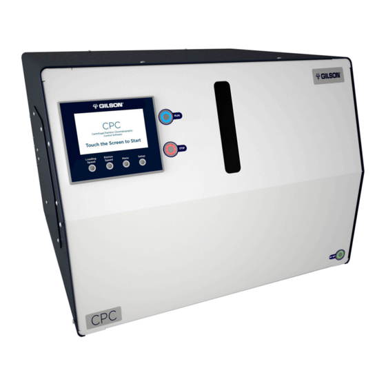
Page 26: Front Panel
(top, left side), four function keys for the touchscreen, and two momentarily illuminated push buttons for rUN and StOp. Figure 11 Front Panel Diagram - Power Button and Power indicator light Display / Touchscreen Figure 12 Front Panel Diagram - Display/touchscreen oPeRAtion Gilson CPC systems... - Page 27 When the power is turned on, the green indicator light inside the power button illuminates. Display/Touchscreen When the Gilson CPC System is used as a standalone unit, the touchscreen enables direct control of the rotors and modification of the working parameters. When the system is controlled with the remote software, the touchscreen is not used and displays the welcome screen.
- Page 28 Figure 17 login screen on-screen Keyboard Only qualified service personnel or certified Gilson partners may access the Setup Screen. NOTICE Changing the advanced settings in this menu without Gilson authorization may damage the Gilson CPC System and void the warranty.
-
Page 29: Start Up
Do not plug in or switch on the instrument when the protective panels are removed. Starting WARNING the rotor without protection may result in serious injury. Power To start/turn on the Gilson CPC System, press the button on the lower right side of the front panel. ● The green indicator light inside the power button will illuminate. -
Page 30: Control The System
Control the System This section explains how to control a Gilson CPC System used as standalone unit. After the instrument is powered on and the control interface opened, use the built-in touchscreen and buttons to control the rotor. Operating Conditions Load the columns with stationary phase at a rotation speed of 500 rpm and perform extrusion (i.e., stationary phase pumping step) at the same rotation speed used for elution... - Page 31 If the setpoint is lower than the current speed, a right arrow appears at the end of the progress bar. Drops may appear on the window during rotation. This originates from greasing during the NOTE manufacturing process and does not affect CPC operations. Gilson CPC systems | UseR’s GUiDe...
- Page 32 To stop the spinning rotor at any time, press the StOp button, which will flash red as the rotor slows. The indicators on the screen and the progress bar show the deceleration of the rotor. When the rotor is completely stopped, the StOp button illuminates red. oPeRAtion Gilson CPC systems...
-
Page 33: Loop Injection With Manual Valve
Loop Injection with Manual Valve When mounted on the Gilson CPC System, use the six-way manual loop injection valve to load the sample into the sample loop and inject it onto the column. This action can be done at any time while the pumps are pumping and the rotor is spinning. -
Page 34: Change The Elution Mode (Asc/Dsc)
Refer to the “Operating Instructions” for more explanations of the manual sample injector. When the Gilson CPC System is coupled with a PLC Purification System, there is no NOTE injection valve on the Gilson CPC System. The injection process is performed on the PLC Purification System, manually or automatically depending on the injection valve model, and managed by the GGC Software. -
Page 35: Power Down
4. Press the power button on the lower right side of the front panel to turn off the instrument. ● The green indicator light inside the power button will switch off. ● The red indicator light inside the StOp button will switch off. ● The touchscreen turns off. Gilson CPC systems | UseR’s GUiDe... -
Page 37: Maintenance
This chapter describes actions that should be performed on a routine basis to ensure the long-term, safe, and trouble-free operation of the Gilson CPC System. The frequency of the maintenance activities is dependent on the nature of the application, such as the solvents used, the volume of the mobile phases delivered by the pump, the level of cleanliness of the facility, etc. -
Page 38: Helpful Hints
The Gilson CPC System should be cleaned occasionally using a dry, clean cloth. If necessary, use a cloth dipped in soapy water. If liquid is accidentally spilled on the Gilson CPC System, wipe it up immediately. If a contamination is suspected, the external surfaces of the instrument should be wiped down with laboratory detergent (alkaline), rinsed with water, and then wiped down with a 10% ethanolic (or IPA) aqueous solution (v/v) to remove any residue. - Page 39 Column and Fluid Path Depending on your use of the Gilson CPC System, it may be necessary to flush the entire fluid path. It is important to clean the column and the fluid path if you won’t be using the system for a while or if you’re using a solution with a high salt concentration for a wash or as...
-
Page 40: Maintenance Schedule
The frequency of the maintenance will vary depending on the system usage and type of sample injected. NOTICE Follow all guidelines listed in this table to avoid damaging the Gilson CPC System. Maintenance Schedule OPERATION FREQUENCY Verify the cleanliness of all liquid containers. -
Page 41: Replace A Seal In A Column Rotary Seal
5. Disconnect the PTFE waste tubing from the sides of the cleaning disc with a 1/4“ spanner (SS nuts). 6. Loosen without pulling out the four central M4 screws of the rotary seal in an alternating criss-cross pattern with a 3 mm Allen wrench (only one turn counter-clockwise). Gilson CPC systems | UseR’s GUiDe... - Page 42 3 mm Allen wrench to disassemble the head and the cleaning disc. Rotary Seal Head Central Screws Rotary Seal Cleaning Disc Figure 30 Rotary seal Assembly Note the positioning of the holes for tubing connection on the head and cleaning disc before NOTE disassembling. mAintenAnCe Gilson CPC systems...
- Page 43 11. Thoroughly clean the seal seat with Isopropyl Alcohol (IPA) or ethanol to remove possible worn seal particles, and then immerse the new seal in IPA for lubrication. 12. Align the new seal over the seal seat of the head or cleaning disc. Gilson CPC systems | UseR’s GUiDe...
- Page 44 15. Briskly push part D with the palm of your hand, inserting the seal into position. Figure 34 Column seal seating instructions 16. Remove the tool and examine the seal to ensure it is properly placed. mAintenAnCe Gilson CPC systems...
- Page 45 Reset below the Seals field to reset the counter and close the Menu screen. When the Gilson CPC System is used for the first time, or after replacing a seal of the rotary seal NOTE assembly, black particles may appear in the waste and fraction collector vessels. This is expected and will go away with continued use.
-
Page 47: Troubleshooting
Chapter 5 trOUBLeShOOtING Chapter 5 | IN thIS Chapter ● Troubleshooting Table ● Error Messages ● Repair and Return Policies Gilson CPC systems | UseR’s GUiDe... -
Page 48: Troubleshooting Table
The following table details some basic symptoms, possible causes, and potential solutions for issues related to Gilson CPC System. If the problem persists after all remedies have been attempted, contact Gilson customer service. Refer to Customer Service on page 14. - Page 49 ● Contact your local Gilson representative ● Check the AC power source Gilson CPC system does not switch the Gilson CPC system is not supplied with voltage ● try a different AC outlet ● Check the AC power cord ●...
-
Page 50: Error Messages
When a Driver Error occurs, the red StOp button light flashes rapidly on the front panel of the instrument and the error number appears on the front panel display. For assistance with resolving an error, contact your local Gilson representative. Refer to the table below for the error text. -
Page 51: Repair And Return Policies
Repair and Return Policies Before Calling Us Your local Gilson representative will be able to serve you more efficiently if you have the following information: ● Serial number and model number of the instruments involved ○ The serial number is located on the left side of the Gilson CPC System ●... -
Page 53: Warranty
WARRAnTY Appendix 6 | General A Gilson CPC System is under warranty to be free from defects in material or workmanship under normal use within the instrument specifications indicated in this user’s guide and under conditions given below. The warranty period is one year from the date of initial shipment of the manufacturer. Note... -
Page 54: Limited Warranty
● Use of clean solvents and containers ● Following the preventative maintenance schedule dAMAGeS nOT COVeRed ● Damaged parts or crushed internal parts caused by improper tightening ● Blocked flow paths caused by improper installation or unsuitable mobile phases WARRAnty Gilson CPC systems... -
Page 55: Replacement Parts And Accessories
RepLACeMenT pARTS And Appendix A | ACCeSSORieS All items listed must only be supplied by Gilson or an agent thereof. Use of alternate parts CAUTION may lead to improper operation of the system or failure to comply with safety or EMC regulations. - Page 56 1/8” tubing (qty. 10) 21041002 Plug, PeeK, 10-32 Miscellaneous PART DESCRIPTION NUMBER 21041003 Fuse, 3.15 A, H 250 V~ 21040150 Fuse, 6.3 A, H 250 V~ 21040160 serial Rs-232 cable male/female RePlACement PARts AnD ACCessoRies Gilson CPC systems...
- Page 57 PeeK, 1/16” oD, 0.75 mm iD, 1 meter 21041016 PeeK, 1/8” oD, 2.0 mm iD, 1 meter 21040171 ss, 1/16” oD, 1.0 mm iD, 1 meter 21040140 ss, 1/8” oD, 2.1 mm iD, 1 meter Gilson CPC systems | UseR’s GUiDe...
- Page 58 Valves PART DESCRIPTION NUMBER 21041017 manual AsC/DsC valve 21041018 manual loop injection Valve 21041019 needle, 16GA, ss for manual loop injection valve 21041020 Rebuild kit for manual loop injection valve RePlACement PARts AnD ACCessoRies Gilson CPC systems...
- Page 59 100 impressive adaptability enables it to compensate for minor damage or unevenness in the flange surface. excellent media resistance makes it the ideal solution for use in the chemical industry. liQUiD ContACt mAteRiAls ContinUeD on PAGe 56 Gilson CPC systems | UseR’s GUiDe...
- Page 60 316l, including weldability and work hardening through cold working. in addition, 316 does not require post‑work annealing to maximize its corrosion resistance, however annealing may be utilized in certain situations. liQUiD ContACt mAteRiAls ContinUeD on PAGe 57 mAteRiAls Gilson CPC systems...
- Page 61 Vespel® description provided by DuPont (www.dupont.com) novaflon® 100 description provided by Frenzelit‑Werke GmbH (www.frenzelit.com) stainless steel, type 316 / 316l descriptions provided by stardust impex (www.stardustimpex.com) Zirconium oxide description provided by Ceramaret sA (www.ceramaret.ch) Gilson CPC systems | UseR’s GUiDe...
- Page 64 Gilson Purification S.A.S. 22, rue Bourseul - ZA du Poteau - F-56890 Saint-Avé, France LT309176-02 www.gilson.com/contactus Original Instructions...
Need help?
Do you have a question about the CPC Series and is the answer not in the manual?
Questions and answers