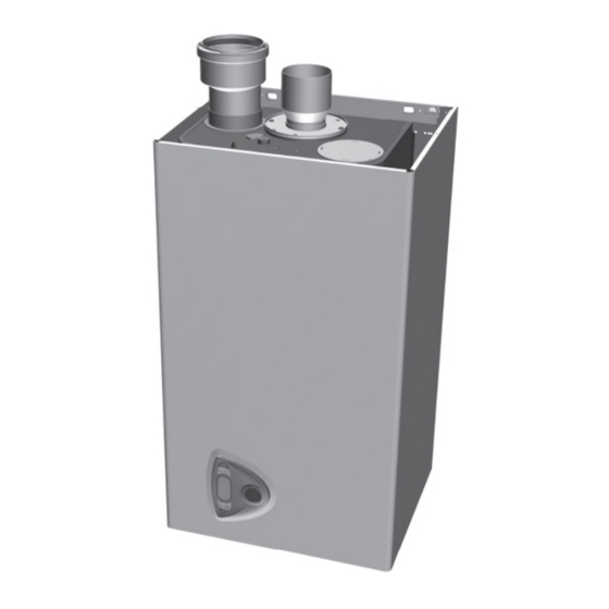
ECR International CHB Application Manual

ECR International CHB Application Manual

Wall mounted gas boiler

Advertisement

Models
CHB/CCB
APPLICATION GUIDE
WALL MOUNTED
GAS BOILER
This manual has been prepared for use with the appropriate Installation, Operation and
Maintenance Manual.
For use with CCB/CHB Boilers ONLY.
Manufactured by:
ECR International Inc.
2201 Dwyer Avenue, Utica, NY 13501
Tel. 800 253 7900
www.ecrinternational.com
PN 240011074 REV C [11/01/2017]

Advertisement

Table of Contents
loading

Summary of Contents for ECR International CHB

  • Page 1 WALL MOUNTED GAS BOILER This manual has been prepared for use with the appropriate Installation, Operation and Maintenance Manual. For use with CCB/CHB Boilers ONLY. Manufactured by: ECR International Inc. 2201 Dwyer Avenue, Utica, NY 13501 Tel. 800 253 7900 www.ecrinternational.com...
  • Page 2 Boiler with Multiple Zone Pumps WITHOUT DHW Interface (Fig. 17) .............. 26 Boiler with Multiple Zone Pumps with DHW Interface (Fig. 18) ..............27 Applications Tables For : CHB - With Indirect Hot Water Tank ...........28 Optional Equipment ........................30 Venting Options .............................30 Outdoor Air Sensor &...
  • Page 3: Important Safety Information

    IMPORTANT SAFETY INFORMATION 1. General 3. Installation shall conform to requirements of Boiler installation shall be completed by qualified agency. See authority having jurisdiction or in absence of such Installation, Operation & Maintenance Manual for additional requirements: • United States information.
  • Page 4 Multiple Zone Pumps, WITHOUT Indirect Tank (CH only) (Fig. 9) Multiple Zone Pumps, WITH Indirect/Sensor (Fig. 10) Multiple Zone Pumps, WITH Indirect Tank/Mechanical Thermostat/Isolation Relay (Fig. 11) Application Tables For : CHB - With Indirect Hot Water Tank PN 240011074 REV C, [11/01/2017]...
  • Page 5 CHB - HYDRONIC PIPING FIGURE 1 - CHB - Single Boiler Primary/Secondary Series Loop Zoned System WITH ZONE VALVES and Optional Indirect Tank PN 240011074 REV C, [11/01/2017]...
  • Page 6 CHB - HYDRONIC PIPING FIGURE 2 - CHB -Single Boiler Primary/Secondary Series Loop Zoned WITH ZONE PUMPS and Optional Indirect Tank PN 240011074 REV C, [11/01/2017]...
  • Page 7 CHB - HYDRONIC PIPING FIGURE 3 - CHB -Single Boiler Primary/Secondary Series Loop PUMPING and Optional Indirect Tank PN 240011074 REV C, [11/01/2017]...
  • Page 8: Chb - Wiring Diagrams

    (Key 155) on CHB terminal strip. See Figure 5. C22.1: Safety Standard for Electrical Installations. A. CHB Single Zone Indirect Storage Tank is NOT used: • Terminals 7 and 8 (Key 155) on CHB terminal strip, shall have two (2) factory supplied resistors wired in NOTICE parallel. Important: •...
  • Page 9 CHB - WIRING DIAGRAMS FIGURE 4 - CHB Boiler with Optional Supply System Pump Single Zone - No Indirect Tank (DHW) CHB BOILER System Supply Pump Connection CH System L1 (Hot) Pump (If Used) Key 307 KEY 370 Key 155...
  • Page 10 CHB/CCB - WIRING DIAGRAM FIGURE 6 - Isolation Relay - Pump Circuit Using System Pump Connections BOILER CONTROL JUNCTION BOX (120VAC) Isolation Relay* System Supply 240011284 Pump Connection 120 VAC RIBU1C POWER SUPPLY CORD 120V/60HZ 120 VAC Power Supply CH System Pump (IF≥1 AMP)
  • Page 11 CHB - WIRING DIAGRAM D. Multi-Zoned Valve System: NOTICE If only Central Heating is required on multi-zone valve Important: application - use factory supplied resistors on Key 155 • Before connecting to Key 72 terminals, terminal strip: remove jumper on terminal block. (Key 72) •...
  • Page 12 CHB - WIRING DIAGRAM FIGURE 7 - CHB - Boiler Zoned System with Multiple ZONE VALVES WITHOUT Indirect Tank Low Volt Room Thermostats Lights Set Priority Switch “OFF” For Central Heating Only Argo AZ- 4CP VALVE VALVE VALVE VALVE Low Voltage Zone Valve(S)
  • Page 13 CHB - WIRING DIAGRAM FIGURE 8 - CHB - Boiler Zoned System with Multiple ZONE VALVES WITH Indirect Tank Low Volt Room Thermostats Lights Set Priority Switch “OFF” Argo AZ- 4CP VALVE VALVE VALVE VALVE Low Voltage Zone Valve(S) System...
  • Page 14 CHB - WIRING DIAGRAM E. Multi-Zone Pump System Using Argo ARM NOTICE Controller: Important: 1 - If Indirect Storage Tank IS NOT applied to a multi-zoned • Before connecting to Key 72 Terminals, remove jumper on piping system: terminal block.
  • Page 15 CHB - WIRING DIAGRAM FIGURE 9 - CHB Boiler WITH MULTIPLE ZONE PUMPS WITHOUT Indirect Tank (DHW) Low Volt Room Thermostats Set Priority Switch “OFF” Argo ARM Zone Pump Control CH Heating Only High Voltage Power Supply 120V/60Hz Zone Pumps...
  • Page 16 CHB - WIRING DIAGRAM FIGURE 10 - CHB Boiler WITH MULTIPLE ZONE PUMPS WITH Indirect Tank (DHW) Low Volt Room Thermostats Set Priority Switch “OFF” Argo ARM Zone Pump Control High Voltage Power Supply 120V/60Hz Zone Pumps System Pump CHB BOILER...
  • Page 17 • Before connecting Low Water Cutoff remove jumper on terminal block. (Key 370) FIGURE 11 - CHB Boiler WITH SECONDARY ZONE PUMPS AND DHW THERMOSTAT, WITH DHW RESISTOR KIT NOTE: ZONE PUMPS WILL SHUTOFF DURING DHW PRIORITY W/ PRIORITY SWITCH ON...
  • Page 18: Single Boiler Primary/Secondary Series Loop Zoned System With Zone Valves (Fig. 12)

    CCB - HYDRONIC PIPING NOTICE Arrange piping to prevent water dripping onto boiler. A. Piping installation, materials, and joining methods shall conform to requirements of authority having jurisdiction or in absence of such requirements: • USA - National Fuel Gas Code, ANSI Z223.1/NFPA 54 •...
  • Page 19 WARNING Burn and scald hazard! Manufacturer requires installation of field supplied anti-scald valve. Failure to follow these instructions could result in death or serious injury. CCB-150 DHW ANTI-SCALD PIPING Piping Legend Boiler Cold Water Supply Tempering Valve Outlet Inlet Return Supply Water Supply...
  • Page 20 CCB - HYDRONIC PIPING FIGURE 12 - CCB Single Boiler Primary/Secondary Series Loop Zoned System WITH ZONE VALVES PN 240011074 REV C, [11/01/2017]...
  • Page 21 CCB - HYDRONIC PIPING FIGURE 13 - CCB -Single Boiler Primary/Secondary Series Loop Zoned WITH ZONE PUMPS PN 240011074 REV C, [11/01/2017]...
  • Page 22 CCB - HYDRONIC PIPING FIGURE 14 - CCB -Single Boiler Primary/Secondary Series Loop PUMPING PN 240011074 REV C, [11/01/2017]...
  • Page 23 C22.1: Safety Standard for Electrical Installations. jumper on terminal block. (Key 370) 2. CCB/Single Zone Single room thermostat (Key 72) will control the internal Wiring Legend CHB/CCB pump and boiler operation. Remove jumper when connecting the thermostat or zone equipment. See Figure 15.
  • Page 24 CCB BOILER - WIRING DIAGRAMS 4. CCB - Using Multi-Zone Valve System NOTICE Boiler call for heat contacts (Key 72) are wired to Argo Zone Important: Control (x-x) terminals. Zone thermostats and zone valves • Before connecting to Key 72 Terminals, are to be wired to the Argo Zone Controller.
  • Page 25 CCB BOILER - WIRING DIAGRAMS 5. CCB Using Multi-Zone Pump System NOTICE Wiring of Argo Control may include Priority Zone Control. Important: • Before connecting to room Key 72 Terminals, Boiler thermostat contacts (Key 72) are wired to Argo ARM remove jumper on terminal block.
  • Page 26: Pump Control

    CCB BOILER - WIRING DIAGRAMS FIGURE 17 - CCB Boiler with Multiple Zone Pumps WITHOUT DHW Interface NOTICE LOW VOLTAGE ROOM THERMOSTATS Important: • Before connecting to Argo Control remove jumper on terminal block. (Key 72) • Before connecting Low Water Cutoff remove jumper on terminal block.
  • Page 27 CCB BOILER - WIRING DIAGRAMS FIGURE 18 - CCB Boiler with Multiple Zone Pumps WITH DHW Interface NOTICE N.O. LOW VOLTAGE ROOM THERMOSTATS (Zone 2-4) Important: FLOW • Before connecting to Argo SWITCH (0.50 GPM) Control remove jumper on terminal block. (Key 72) •...
  • Page 28 APPLICATION TABLES FOR : CHB - INDIRECT HOT WATER TANK 3/4" PIPE PRESS. HEAD EQUIV. INTERNAL FROM BOILER PIPE LENGTH PUMP (FT - H2O) (FEET) (GPM) 10 FT. 30 FT. 50 FT. 1" PIPE PRESS. HEAD EQUIV. INTERNAL PIPE LENGTH...
  • Page 29 APPLICATION TABLES FOR : CHB - INDIRECT HOT WATER TANK PN 240011074 REV C, [11/01/2017]...
  • Page 30: Venting Options

    VENTING OPTIONS TYPE I - VENTING (ACCEPTABLE) TYPE I- VENTING (ACCEPTABLE) Outside Air Outside Air Optional Optional Boiler Boiler Tank Tank TYPE I - VENTING (NON-ACCEPTABLE) TYPE I- VENTING (NON-ACCEPTABLE) Outside Air Outside Air Optional Optional Boiler Boiler Tank Tank PN 240011074 REV C, [11/01/2017]...
  • Page 31: Optional Equipment

    OPTIONAL EQUIPMENT - SENSORS Optional Equipment Outdoor Air Sensor, if used. A. See Chart 1 for sensor data. Sensor part number FE013018X0. B. Locate outdoor sensor to protect against wind and direct sunlight. Mounting instructions provided with sensor. C. Maximum wire length is 100 ft (30m) for 22 ga. wire, or 150 ft (45m) for 18 ga. wire. D.
  • Page 32: Manufacturer Recommended Strainer

    OPTIONAL EQUIPMENT - MANUFACTURER RECOMMENDED STRAINER PN 240011074 REV C, [11/01/2017]...
  • Page 33: Low Water Cutoff

    OPTIONAL EQUIPMENT - LOW WATER CUTOFF Low Water Cut Off - Heating Only and Combi Boilers These guidelines are supplied when necessary to install an additional Low Water Cut Off (LWCO), for sensing a low water level condition in a boiler, as required by the Authority Having Jurisdiction.
  • Page 34 OPTIONAL EQUIPMENT - LOW WATER CUTOFF LWCO Wiring Diagram 138 - Optional Outdoor Sensor 155 - Optional Indirect Tank Sensor 370 - Field Source LWCO Modulating fan Heating circulating pump DHW temperature sensor (see kit) NOTICE Gas valve Modulation Regulator (24V) *IMPORTANT: •...
  • Page 35 OPTIONAL EQUIPMENT - LOW WATER CUTOFF Piping Diagram - LWCO Location Arrange piping to prevent water Note dripping onto boiler. Low Water Cutoff (LWCO) Position Above Top of Boiler Illustrations are meant to show Air Vent system piping concept only. Installer Note is responsible for all equipment and detailing required by authority having...
  • Page 36 OPTIONAL EQUIPMENT - LOW WATER CUTOFF Low Water Cutoff - Detail PN 240011074 REV C, [11/01/2017]...
  • Page 37: Addendum - Instructions

    Sealed Combustion Kit Instructions (37711601) - For Kit #5612601........45 Control Board Replacement Kit Instructions (615000134)..........46-47 Retaining Clip Removal Caution (615000136)..............48-49 Altitude Affects on CHB-100, CHB-130, CHB-150 and CCB-150..........50 LP Conversion Kit Instructions..................51-53 DHW Resistor Harness and Relay Kit (550003082)............54-57 Combustion Cover Replacement Kit Instructions..............58...
  • Page 38 DOMESTIC HOT WATER SENSOR KIT INSTRUCTIONS FOR CHB-100, CHB-130, CHB-150 Kit #550002958 Kit installation shall be completed by qualified agency. Figure 1 - Slide Sensor Into well of Indirect Tank WARNING Fire, explosion, asphyxiation and electrical shock hazard. Improper installation could result in death or serious injury.
  • Page 39 DOMESTIC HOT WATER SENSOR KIT Restore power to boiler. Boiler will automatically DOMESTIC HOT WATER SENSOR KIT recognize the sensor. FOR CHB-100/ CHB-130/ CHB150 #550002958 See Installation, Operation & Maintenance Manual for adjusting DHW tank temperature and operation. DESCRIPTION PART # Resume operation using Installation, Operation &...
  • Page 40 DOMESTIC HOT WATER SENSOR KIT WIRING DIAGRAM Figure 4 - Wiring Diagram *138 - Optional Outdoor Sensor kOhm *155 - Optional Indirect Tank Sensor If Key 155 is 138 Optional Outdoor Sensor *307 - CH System Pump (if used) used remove 155 Optional Indirect Tank Sensor *370 - Field Source LWCO kOhm...
  • Page 41 DOMESTIC HOT WATER SENSOR KIT Figure 5 - Low Voltage Terminal Strip, CHB-130 Figure 6 - Low Voltage Terminal Strip Removed from Shown Boiler, CHB -130 Shown Low Voltage Low Voltage Terminal Strip Terminal Strip Removed Temperature Deg F Resistance in Ohms...
  • Page 42 INSTRUCTIONS AND WIRING DIAGRAM FOR ADDING EXTERNAL PUMP TO CHB/CCB BOILERS (Without Factory Pump Terminals) Installation shall be completed by qualified agency. An external pump is necessary for the following conditions: • The central heating circuit exceeds 8 ft of total head WARNING loss.
  • Page 43 Figure 1 - Optional External Pump/Relay Wiring Call for Heat ARGO Controller AR822-II Ref. Key 72 Important: Before connecting the Argo Controller, remove supplied jumper on terminal block. 15VA Transformer Relay Factory Installed Jumper [DO NOT REMOVE] External Circulator Pump Field Installed Wiring Argo contact rating = 7 Amp Maximum...
  • Page 44: Installation Instructions

    Sealed Combustion Termination Kit # 5612601 Installation Instructions Installation Instructions: Kit installation shall be completed by qualified agency. Use supplied template to cut a hole through the wall. Secure template to inside wall. WARNING NOTICE Fire, explosion, asphyxiation and electrical shock hazard.
  • Page 45 CONTROL BOARD (DBM34A) KIT #FE3980B851 REPLACEMENT INSTRUCTIONS Kit installation shall be completed by qualified agency. Figure 1 WARNING Fire, explosion, asphyxiation and electrical shock hazard. Improper installation could result in death or serious injury. Read this instruction and understand all requirements, including requirements of authority having jurisdiction, before beginning Remove (2) installation.
  • Page 46 Setting Curve Selection Default = 2 CHB-100 CHB-130 CHB-150 CCB-150 Table - 3 Configuration Menu CCB-150 CHB-130 CHB-100 CHB-150 Power Selection Offset max. setpoint air signal Burner selection Offset min. setpoint air signal PN 3541F682 REF #615000134, REV C [02/2016]...
  • Page 47 CAUTION DO NOT remove retaining clips on field installed water fittings. Removed fittings CANNOT be reinstalled. DO NOT solder on threaded joints. Heating the fitting will cause O-ring joint failure causing leaks. DO NOT REMOVE RETAINING CLIPS ON WATER FITTINGS DO NOT REMOVE CLIP RIGHT SIDE CLIP - INSIDE BOILER JACKET Control is...
  • Page 48 Manufacturer recommended piping method: Use piping accessories as shown in diagram below. Do any necessary soldering away from the boiler, then thread soldered assembly to Boiler connections. PIPING DIAGRAMS Female Copper Fitting Union Copper Pipe ( 6” min. length manufacturer recommended) Copper Pipe Union...
  • Page 49 Altitude Affects on CHB-100, CHB-130, CHB 150 and CCB-150 Above curves show affect altitude will have on boiler delivery. Manufacturer has tested this boiler at altitude (sea level to 8,000 ft.) and determined that standard (ANSI) derate input practices of re-orificing are not required for these models.
  • Page 53 CHB BOILER DHW RESISTOR HARNESS AND RELAY KIT 550003082 For use with Argo ARM Zone Pump Control Kit installation shall be completed by qualified agency. Kit Contents: Description Qty. WARNING DHW Resistor Harness Fire, explosion, asphyxiation and electrical shock Isolation Relay (24 VAC) hazard.
  • Page 54 CHB BOILER - DHW RESISTOR HARNESS KIT Multi-Zone Pump System with DHW Tank FIGURE 1 - Isolation Relay Thermostat and Isolation Relay If DHW tank thermostat is applied to multi-zoned pump application secondary pump operation is controlled by Argo priority switch position.
  • Page 55 CHB BOILER - DHW RESISTOR HARNESS KIT FIGURE 2 - CHB Boiler WITH SECONDARY ZONE PUMPS and DHW THERMOSTAT NOTE: ZONE PUMPS WILL SHUTOFF DURING DHW PRIORITY W/ PRIORITY SWITCH ON Low Voltage Isolation Relay Room Thermostats Thermostat 120V W/BLK...
  • Page 56 CHB BOILER - DHW RESISTOR HARNESS KIT FIGURE 4 - CHB -Single Boiler Primary/Secondary Series Loop Zoned WITH ZONE PUMPS and Optional Indirect Tank PN 240011270 REV B [03/11/2016]...
  • Page 57 CCB/CHB REPLACEMENT COMBUSTION COVER KIT INSTRUCTIONS 550003447 - CCB/CHB 150 550003448 - CHB 100 550003449 - CHB 130 Kit installation shall be completed by qualified agency. Install new outer combustion cover in place. Take care to WARNING ensure left and right sides are tucked behind the vertical rails.
  • Page 58 NOTES...
  • Page 59 NOTES...
  • Page 60 ECR International Inc. 2201 Dwyer Avenue, Utica, NY 13501 All specifications subject to change without notice. ©2017 ECR International, Inc. Tel. 800 253 7900 PN 240011074 REV. C [11/01/2017] www.ecrinternational.com...

This manual is also suitable for:

CcbChb 150Chb 100Chb 130Ccb 150

Table of Contents