ECR International CCB-150 Installation, Operation & Maintenance Manual
Combi
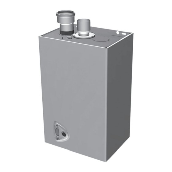
wall mounted
gas boiler
Hide thumbs
Also See for CCB-150:
- Installation, operation & maintenance manual (92 pages) ,
- Application manual (60 pages)

Related Manuals for ECR International CCB-150


Summary of Contents for ECR International CCB-150
- Page 1 Model CCB-150 COMBI WALL MOUNTED GAS BOILER INSTALLATION, OPERATION & MAINTENANCE MANUAL Manufactured for: ECR International, Inc. 2201 Dwyer Avenue, Utica NY 13501 web site: www.ecrinternational.com P/N# 240010632, Rev. B [07/17/2014]...
- Page 2 DIMENSIONS Figure 1 - Overall Dimensions Top View Side View Front View Rear View 1 = 1“ MPT Supply Water to Heating System (Out) 2 = 3/4” MPT Tap Water Outlet 3 = 3/4” FPT Gas Inlet 4 = 3/4” MPT Tap Water Inlet 5 = 1”...
-
Page 3: Table Of Contents
TABLE OF CONTENTS 1 - Introduction ........................4 2 - Important Safety Information ................... 5 3 - General view and main components .................. 6 4 - Locating Boiler ....................... 9 5 - Hydronic Piping ......................11 6 - Combustion Air And Vent Piping - Category I (Chimney Vent) ..........15 6 - Combustion Air And Vent Piping of direct vent and Category III .......... -
Page 4: Introduction
• Integral Dual Limit. Information and specifi cations outlined in this manual in effect at the time of printing of this manual. ECR International, Inc. reserves the right to discontinue, change specifi cations or system design at any time without... -
Page 5: Important Safety Information
2 - IMPORTANT SAFETY INFORMATION 2.1 General 2.3 Installation shall conform to requirements of Boiler installation shall be completed by qualifi ed agency. authority having jurisdiction or in absence of such See glossary for additional information. requirements: • United States •... -
Page 6: General View And Main Components
3 - GENERAL VIEW AND MAIN COMPONENTS Figure 2 Component Listing... - Page 7 3 - GENERAL VIEW AND MAIN COMPONENTS Item Description Number Sealed Chamber Gas Inlet Domestic Hot Water (DHW) Outlet Domestic Cold Water (DHW) Inlet Supply System System Return Modulating Fan Combustion Chamber Burner Assembly Burner Combustion Chamber Insulation Copper Heat Exchanger Exhaust Manifold Exhaust Outlet Manifold Heating circulating pump...
- Page 8 3 - GENERAL VIEW AND MAIN COMPONENTS WARNING Fire, explosion, asphyxiation and electrical shock hazard. Disconnect electrical power supply and turn off gas at shutoff valve before attemting to remove boiler jacket. Failure to follow these instructions could result in death or serious injury.
-
Page 9: Locating Boiler
4 - LOCATING BOILER 4.1 Boiler Location Considerations Figure 5 - Boiler Clearances • Ambient room temperature always above 32°F (0°C) to prevent freezing. • Approved for installation in closets. • Protect gas ignition system components from water (dripping, spraying, rain, etc.) during operation and service (circulator replacement, control replacement, etc.). - Page 10 4 - LOCATING BOILER Pre-pipe supply and return water connections Figure 6 - Wall Mounting Bracket with factory fi ttings before wall mounting. 4.3 Wall Mounting 2⅜” 2⅜” Mount boiler on wall using wall mounting bracket included (2.4cm) (2.4cm) with unit. •...
-
Page 11: Hydronic Piping
5 - HYDRONIC PIPING 5.1 General Conditioning chemicals must ensure complete deoxygenation of water and contain specifi c protective agents for yellow • Install piping in accordance with authority having jurisdiction. metals (copper and its alloys), anti-fouling agents for NOTICE limescale at least up to 150 ppm CaCO3, pH neutral stabilizers and, in low temperature systems, specifi... - Page 12 5 - HYDRONIC PIPING Figure 7 - Safety Relief Valve & Air Vent WARNING (Viewed from front of boiler) Burn and Scald Hazard. Safety relief vlave could discharge steam or hot water during operation. Install discharge piping per these instructions. Failure to do so could result in death or serious injury.
- Page 13 5 - HYDRONIC PIPING Figure 8 - Safety Relief Valve Discharge Piping Safety Relief Valve Gas Shutoff Valve in Open position Check Local Codes for Maximum Distance to Floor...
- Page 14 5 - HYDRONIC PIPING Figure 9 - Hydronic Piping - Plumbing circuit 8 Domestic Hot Water Outlet 9 Domestic Cold Water Inlet 10 Heating System Supply 11 Heating System Return 27 Copper Exchanger For Heating And Hot Water 32 Heating Circulating Pump 36 Automatic Air Vent 42 DHW Temperature Sensor 95 Diverter Valve...
-
Page 15: Combustion Air And Vent Piping - Category I (Chimney Vent)
6 - COMBUSTION AIR AND VENT PIPING - CATEGORY I (CHIMNEY VENT) Vent connector from boiler to chimney should run as WARNING directly as possible with as few elbows as possible. Boiler and venting installations shall be performed Common venting shall not be allowed. Boiler and by a qualifi... -
Page 16: Removing Existing Boiler From Common Venting System
6 - COMBUSTION AIR AND VENT PIPING- CATEGORY I (CHIMNEY VENT) 6.2 Minimum Vent Pipe Clearance After it has been determined that each appliance remaining connected to the common venting system • Use Type B vent pipe through crawl space. Where vent properly vents when tested as outlined above, return pipe passes through combustible wall or partition, use doors, windows, exhaust fans, fi... -
Page 17: Combustion Air And Vent Piping Of Direct Vent And Category Iii
6 - COMBUSTION AIR AND VENT PIPING OF DIRECT VENT AND CATEGORY III Induced Draft Boilers D. The venting system shall terminate at least 3 feet 0.9m) above any forced air inlet located within Horizontal (Category III) venting systems installation 10 feet (3m). - Page 18 6 - COMBUSTION AIR AND VENT PIPING OF DIRECT VENT AND CATEGORY III If the horizontal vent must go through a crawl space or WARNING other unheated space, the cool temperatures will likely Vent extending through exterior wall shall not cause the fl...
-
Page 19: Combustion Air And Ventilation
6 - COMBUSTION AIR AND VENTILATION Provide combustion air and ventilation air in accordance • All Outdoor Air. Provide permanent opening(s) with the section “Air for Combustion and Ventilation,” of the communicating directly or by ducts with outdoors. National Fuel Gas Code, ANSI Z223.1/NFPA 54, or Sections ◊... - Page 20 6 - COMBUSTION AIR AND VENT PIPING Figure 11 - Horizontal Venting Clearances NOTICE Maintain 12” (30cm) US, 18” (46cm) Canada Figure 12 - Two Pipe Venting clearance above highest anticipated snow level or grade. = Combustion Air / = Venting)
- Page 21 6 - COMBUSTION AIR AND VENT PIPING NOTICE Figure 13 - Chimney Venting with Room Air Single Wall Refer to section 6.1, numbers 3 through 12, page 15 of this manual for proper installation. = Combustion Air / = Venting) Figure 14 - Chimney Venting with Outside Air Single Wall = Combustion Air /...
-
Page 22: Gas Supply Piping
7 - GAS SUPPLY PIPING Figure 15 Manual Main Gas Shutoff Valve CAUTION Outside Boiler Jacket WHAT TO DO IF YOU SMELL GAS With Manufacturer Suggested Piping With Drip Leg • Do not try to light any appliance. • Do not touch any electrical switch; do not use any phone in your building. -
Page 23: Electrical Connections
8 - ELECTRICAL CONNECTIONS Figure 16 - Terminal Block WARNING Electrical shock hazard. Turn OFF electrical power supply at service panel before making electrical connections. Failure to do so could result in death or serious injury. 8.1 General Electrically bond boiler to ground in accordance with requirements of authority having jurisdiction. -
Page 24: Start Up Procedure
9 - START UP PROCEDURE 9.1 Fill Boiler With Water And Purge Air WARNING NOTICE Asphyxiation hazard. Carbon monoxide is odorless, To maintain boiler effi ciency and prevent boiling tasteless, clear colorless gas, which is highly toxic. inside the heat exchanger, fl ush entire heating Carbon monoxide production shall not exceed system until clean. - Page 25 9 - START UP PROCEDURE 9.6 Check Combustion Figure 17 - Test Ports Natural Gas Vent Gases Measure input. English unitsTurn off gas to all other Test Port appliances. • Activate some heating zones to dissipate heat. • Set boiler on high fi re. •...
-
Page 26: Operating Instructions
10 - OPERATING INSTRUCTIONS WARNING CAUTION If you do not follow these instructions WHAT TO DO IF YOU SMELL GAS exactly, a fi re or explosion may result • Do not try to light any appliance. causing property damage, personal injury •... -
Page 27: Control Panel
10 - OPERATING INSTRUCTIONS 10.3 Checks During Operation 10.5 Indicator During Operation • Check for leaks in piping systems. Correct immediately Heating if found. Call for heat (generated by Room Thermostat) is indicated • Check the effi ciency of the fl ue gases and combustion by hot air fl... - Page 28 10 - OPERATING INSTRUCTIONS Boiler Ignition Summer/Winter Switchover Supply unit with electricity. Press the button for 2 seconds. Display will activate Summer symbol (see item 10 on the control panel display). Boiler will deliver tap water only. Boiler ignition Antifreeze system stays on. For 120 seconds display will show FH which identifi...
- Page 29 10 - OPERATING INSTRUCTIONS ECO/COMFORT selection The unit has a function that ensures a high domestic hot water delivery speed and maximum comfort for the user. When the device is activated (COMFORT mode), the water contained in the boiler remains hot, ensuring faster availability of domestic hot water.
- Page 30 10 - OPERATING INSTRUCTIONS Compensation curve and curve offset Press the button (see item 6 on the control panel display) for 5 seconds once to display the actual compensation curve, which can be modifi ed with the DHW buttons (see items 1 and 2 on the control panel display).
- Page 31 10 - OPERATING INSTRUCTIONS Example of parallel compensation curve shift Press the button (see item 6 on control panel display) for 5 seconds again to exit parallel curve adjustment mode. If the room temperature is lower lower than the required value, it is advisable to set a higher order curve and vice versa.
- Page 32 10 - OPERATING INSTRUCTIONS Water system pressure adjustment The fi lling pressure with system cold, read on the boiler water gauge, must be approximately 11 psi. If the system pressure falls to values below minimum, the boiler control will activate fault F37. Low system pressure fault Once the system pressure is restored, the boiler will activate the 120-second air venting cycle indicated on the...
-
Page 33: General Maintenance And Cleaning
11 - GENERAL MAINTENANCE AND CLEANING 11.1 Beginning of Each Heating Season 11.2 Annual Shut Down Procedure • Check boiler area is free from combustible materials, • Follow instructions “To Turn Off Gas To Appliance” unless gasoline, and other fl ammable vapors and liquids. boiler is also used to supply domestic hot water. -
Page 34: Ratings And Capacities
12 - RATINGS AND CAPACITIES... -
Page 35: Ratings And Capacities
(1)(3) Maximum Minimum (MBH) (1)(2) CCB-150 85.0 1000 Btu/hr (British Thermal Units Per Hour) Heating Capacity and AFUE (Annual Fuel Utilization Effi ciency) are based on DOE (Department of Energy) test procedures. Net AHRI Ratings based on piping and pickup allowance of 1.15. Contact Technical Support before selecting boiler for installations having unusual piping and pickup requirements, such as intermittent system operation, extensive piping systems, etc. - Page 36 12 - RATINGS AND CAPACITIES Diagrams Pressure - power diagrams “wc CCB 150 13 14 15 16 17 18 19 20 21 22 23 24 25 26 27 28 29 30 31 32 33 34 35 36 37 38 39 40 41 42 44 45 A LPG B NATURAL GAS Losses of load / head of circulators...
-
Page 37: Trouble Shooting
13 - TROUBLE SHOOTING Diagnostics The boiler is equipped with an advanced self-diagnosis system. In case of a boiler fault, the display will fl ash indicating the fault code. There are faults that cause permanent shutdown (marked with the letter “A”): to restore operation just press the RESET button (detail 6 - Section 10.4, Control, page 25) for 1 second or RESET on the optional remote timer control if installed;... -
Page 38: Wiring Diagram
WIRING DIAGRAM 370 - Field Source LWCO 138 - Optional Outdoor Sensor 120Vac 60Hz DBM34 + 15V G N D O U T + 5 V Important: Before connecting the room thermostat, remove the jumper on terminal block. 16 Modulating fan 114 Water pressure switch 32 Heating circulating pump 136 Flow meter... -
Page 40: Repair Parts List
REPAIR PARTS LIST Part Number Description FE3980B990 CASING "CTR"... - Page 41 REPAIR PARTS LIST Part Number Description FE3980C200 KIT CONTROL BOX FE3980B850 KIT CONTROL BOARD DBM34 FE3980C210 KIT FRONT COVER "CTR" FE3980B840 KIT PRESS.TEMP. GAUGE FE3980C330 KIT WIRING FE3980C220 KIT MONO CABLE EL.
- Page 42 REPAIR PARTS LIST...
- Page 43 REPAIR PARTS LIST Part Number Description FE3980C000 KIT GASKETS SET FE3980C010 KIT 20 GASKET ORING FE3980C020 KIT 10 CLIP FE3980C030 MONO HEAT EXCHANGER FE3980C040 SENOR TEMP DP FE3980C340 SENFOR TEMP 14 FE3980C350 5 FLOW CONTROLLER FE3980C360 KIT FLOWMETER ELTEK FE3980C370 x5 H2O FILTERS FE3980C410 KIT NPT ADAPTERS...
- Page 44 REPAIR PARTS LIST...
- Page 45 REPAIR PARTS LIST Part Number Description FE3980B930 KIT GASKETS SET FE3980C090 PRESSURE TEST POINT "VENTURI" FE3980C100 FAN GASKET FE3980B940 FE3980C110 COMBUSTION CHAMBER INSULATION FE3980C120 IGNITION ELECTRODE FE3980C130 BURNER 17 R.m. FE3980B960 GAS VALVE VGU 54S FE3980C140 17 INJECTOR 1.35mm NG FE3980C150 17 INJECTOR 0.85mm LP FE3980C160...
- Page 46 NOTES...
- Page 47 NOTES...
- Page 48 ECR International, Inc 2201 Dwyer Avenue, Utica NY 13501 web site: www.ecrinternational.com...
Need help?
Do you have a question about the CCB-150 and is the answer not in the manual?
Questions and answers
How do I change the water filters? c09 fe3980c370 page 87 x5 filters h20
Model CCB-150 Combo Wall Mounted Gas Boiler and Water Heater
When turning on the hot water tap, the heater didn't start. Looked like no ignition and gas did not turn on. Sometimes we can hear relay clicking sound, trying to start the gas I think but unable to. After press the reset, it start the ignition and turning on the gas and boiler start to heat up.
Ignition failure in the ECR International CCB-150 heater when turning on the hot water tap could be due to the following reasons:
1. Gas Supply Issue – Ensure the gas valve is open and supplying gas to the boiler.
2. Air in Gas Line – If the system was recently installed or serviced, air in the gas line might prevent ignition.
3. Faulty Ignition System – A malfunctioning igniter or flame sensor could prevent the boiler from lighting.
4. Blocked or Dirty Burners – Dirt or debris on the burners can interfere with ignition.
5. Control Panel Settings – Verify that the boiler is not in Summer Mode, which only provides tap water and may affect ignition behavior.
6. Low Water Pressure – Insufficient water pressure can prevent proper operation.
7. Electrical Issues – Ensure the boiler has power and no wiring issues are present.
Checking these areas can help diagnose and resolve the issue.
This answer is automatically generated