Table of Contents
Advertisement
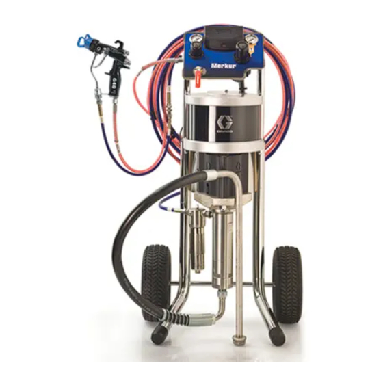
Instructions - Parts
Merkur
Assembly
For high-performance finishing and coating applications in hazardous or non-hazardous
locations. For professional use only.
Important Safety Instructions
Read all warnings and instructions in this manual.
Save these instructions.
See page 4 for model information, including maximum work-
ing pressure.
®
Pump
312794F
EN
TI12811a
ll 2 G
Advertisement
Table of Contents

Related Manuals for Graco Merkur W10CAS


Summary of Contents for Graco Merkur W10CAS
- Page 1 Instructions - Parts ® Merkur Pump 312794F Assembly For high-performance finishing and coating applications in hazardous or non-hazardous locations. For professional use only. Important Safety Instructions Read all warnings and instructions in this manual. Save these instructions. See page 4 for model information, including maximum work- ing pressure.
- Page 2 Shutdown and Care of the Pump ... 12 Graco Information ......32...
-
Page 3: Pump Part Number Matrix
Pump Part Number Matrix Pump Part Number Matrix Check your pump’s identification plate (ID) for the 6-digit part number. Use the following matrix to define the construction of your pump, based on the six digits. For example, Part No. W 1 5 A A S represents a wet cup pump (W), 15 to 1 ratio (15), 25 cc lower (A), 3 UHMWPE/2 PTFE pack- ings with chromex rod coating, no data monitoring, low noise exhaust (A), and stainless steel construction (S). -
Page 4: Pump Models
Pump Models Pump Models Maximum Fluid Flow Rate Displacement Working Pressure at 60 cpm Fluid Fluid Model, Series Motor Pump psi (MPa, bar) gpm (lpm) Inlet Outlet Air Inlet W10CAS, Series A M04LN0 LW075A 1000 (6.9, 69) 1.2 (4.5) 3/4 in. npt 3/8 in. npt 1/4 npt(f) W10CBS, Series A M04LT0 W15AAS, Series A M02LN0 LW025A... -
Page 5: Warnings
Warnings Warnings The following warnings are for the setup, use, grounding, maintenance, and repair of this equipment. The exclama- tion point symbol alerts you to a general warning and the hazard symbol refers to procedure-specific risk. Refer back to these warnings. Additional, product-specific warnings may be found throughout the body of this manual where applicable. -
Page 6: Related Manuals
Related Manuals WARNING PRESSURIZED EQUIPMENT HAZARD Fluid from the gun/dispense valve, leaks, or ruptured components can splash in the eyes or on skin and cause serious injury. • Follow Pressure Relief Procedure in this manual, when you stop spraying and before cleaning, checking, or servicing equipment. -
Page 7: Component Identification
Component Identification Component Identification ti11700a . 1. Component Identification Key: Ground Wire TSL Reservoir Wet Cup (not visible, under TSL reservoir) Fluid Outlet Fluid Inlet Lower Cylinder Upper Cylinder Tie Rod Shield Displacement Pump Adapter Tie Rod Coupling Nut Jam Nut Air Motor 312794F... -
Page 8: Installation
Always use Genuine Graco Parts and Accessories, available from your Graco distributor. If you supply your own accessories, be sure they are adequately sized and pressure-rated for your system. -
Page 9: Mount The Pump
• Pump air regulator (H): controls pump speed and outlet pressure. Locate it close to the pump. Mount the pump only to Graco wall bracket 15T795, or • Air line filter (B): removes harmful dirt and mois- to a Graco cart, available from your distributor. Pump ture from compressed air supply. -
Page 10: Typical Installation
. 4, page 11) Pump Air Pressure Regulator Pump Fluid Inlet Solenoid Release Button Suction Hose (not visible) Fluid Drain Valve Gun Swivel G15 Spray Gun Shown with Supply Hose ti12800a . 3. Typical Installation. (Graco Cart-Mounted Package Shown.) 312794F... -
Page 11: Operation
1. Engage the trigger lock. 2. Close the bleed-type master air valve. Before starting, fill wet cup (T) 1/3 full with Graco Throat 3. Disengage the trigger lock. Seal Liquid (TSL) or compatible solvent. 4. Hold a metal part of the gun firmly to a grounded metal pail. -
Page 12: Prime And Adjust The Pump
Operation Prime and Adjust the Pump 12. Use the air regulator to control the pump speed and the fluid pressure. Always use the lowest air pres- sure necessary to get the desired results. Higher 1. Lock gun trigger. Remove tip guard and spray tip pressures cause premature tip/nozzle and pump from gun. -
Page 13: Maintenance
11. Clean inside and outside of suction tube. Read all Warnings. Follow all Grounding instructions. See page 8. Wet Cup Fill the wet cup one-half full with Graco Throat Seal Liq- Flush the pump: uid (TSL). Maintain level daily. •... -
Page 14: Troubleshooting
Troubleshooting Troubleshooting NOTE: Check all possible problems and causes before disassembling the pump. Relieve the pressure before checking or servicing the equipment. Problem Cause Solution Pump output low on both strokes. Restricted air supply lines. Clear any obstructions; be sure all shutoff valves are open;... -
Page 15: Repair
• Always use Genuine Graco Parts and Accessories, available from your Graco distributor. If you supply ti12812a ti12813a your own accessories, be sure they are adequately sized and pressure rated for your system. -
Page 16: Reconnect The Displacement Pump
Repair Reconnect the Displacement 6. Align fluid outlet as shown and tighten the jam nut. Pump 7. Align the TSL reservoir (7) and push it down into place. 1. Tilt the air motor onto its back, then hand turn the displacement pump into the adapter plate. -
Page 17: Disconnect The Air Motor
Repair Disconnect the Air Motor See manual 312796 for air motor service and parts information, 1. Flush the pump, if possible. (See page 13.) Relieve the pressure. (See page 11.) Reconnect the Air Motor 2. Disconnect the air and fluid hoses, the ground wire (13), and the tie rod shield (11). -
Page 18: Pump Parts
Pump Parts Pump Parts Torque varies by air motor size. M02xxx: 5-10 ft-lb (7-13.5 N•m) All others: 50-55 ft-lb (68-75 N•m) Torque varies by air motor size. M02xxx: 15-20 ft-lb (20-27 N•m) All others: 50-60 ft-lb (68-81 N•m) Torque varies by displacement pump size. 25 cc: 23-26 ft-lb (31-35 N•m) All others: 75-80 ft-lb (102-108 N•m) Torque to 70-75 ft-lb (95-102 N•m) - Page 19 Pump Parts Pump Parts NOTES: • For parts that vary by model, see page 20. • For Flush Kit Pumps 262287 and 262392, see man- ual 310863 for additional parts information. • For Flush Kit Pump 257463, see manual 313289 for additional parts information.
-
Page 20: Parts That Vary By Model
Pump Parts Parts That Vary by Model Motor Tie Rod Piston TSL Reservoir Shield Motor Diam. Displacement Pump Jam Nut (7, includes Adapter (11, includes Drip Shield Model (in.) Pump (2) Adapter (3) o-ring) screw) (12) W10CAS M04LN0 LW075A 15R978 24A636 24A623 15M675... -
Page 21: Repair Kits
Repair Kits Repair Kits LW025A LW050A LW075A 2.5 in. 3.5 in. 3.5 in. 6-7.5 in 3.5 in. 6-7.5 in Kit Description motor motor motor motor motor motor LW100A LW125A LW150A Wet-Cup O-Ring Package of 10 24A630 24A631 24A631 24A632 24A633 24A633 Coupling Collars (10) 24A618... -
Page 22: Performance Charts
Performance Charts Performance Charts Model W10xxx 10:1 Ratio, 75 cc/cycle Cycles per Minute 1000 (7, 70) (0.45) (0.4) (5.5, 55) (0.34) (0.28) (4, 40) (0.23) (3, 30) (0.17) (0.1) (1.4, 14) (.06) (3.8) (2.3) (4.5) (0.75) (3.0) (1.5) Fluid Flow gpm (lpm) tested in No. 10 weight oil = 100 psi (0.7 MPa, 7 bar) = 70 psi (0.5 MPa, 5 bar) = 40 psi (0.3 MPa, 3 bar) - Page 23 Performance Charts Model W15Bxx 15:1 Ratio, 50 cc/cycle Cycles per Minute 1600 (0.5) (11, 110) 1400 (0.45) (10, 100) 1200 (0.4) (8, 80) (0.34) 1000 (7, 70) (0.28) (5.5, 55) (0.23) (4, 40) (0.17) (3, 30) (0.1) (1.4, 14) (.06) (0.4) (0.8) (1.1)
- Page 24 Performance Charts Model W18xxx 18:1 Ratio, 125 cc/cycle Cycles per Minute 2000 (14, 140) (1.1) 1600 (11, 110) (0.9) 1200 (8, 80) (0.6) (5.5, 55) (0.3) (3, 30) (3.8) (1.9) (7.6) (5.7) Fluid Flow gpm (lpm) tested in No. 10 weight oil = 100 psi (0.7 MPa, 7 bar) = 70 psi (0.5 MPa, 5 bar) = 40 psi (0.3 MPa, 3 bar)
- Page 25 Performance Charts Model W24xxx 24:1 Ratio, 150 cc/cycle Cycles per Minute 3000 (2.0) (21, 210) 2500 (1.7) (17, 170) (1.4) 2000 (14, 140) (1.1) 1500 (10, 100) (0.9) 1000 (7, 70) (0.6) (3, 30) (0.3) (5.7) (7.6) (9.5) (1.9) (3.8) Fluid Flow gpm (lpm) tested in No.
- Page 26 Performance Charts Model W30Axx 30:1 Ratio, 25 cc/cycle Cycles per Minute 3000 (0.5) (21, 210) (0.45) 2500 (17, 170) (0.4) 2000 (0.34) (14, 140) (0.28) 1500 (10, 100) (0.23) 1000 (0.17) (7, 70) (0.1) (3, 30) (.06) 0.05 0.25 0.35 0.15 (1.1) (0.4)
- Page 27 Performance Charts Model W36xxx 36:1 Ratio, 100 cc/cycle Cycles per Minute 4000 (1.7) (28, 280) 3500 (24, 240) (1.4) 3000 (21, 210) 2500 (1.1) (17, 170) 2000 (14, 140) (0.9) 1500 (10, 100) (0.6) 1000 (7, 70) (0.3) (3, 30) (2.3) (3.0) (5.3)
- Page 28 Performance Charts Model W48xxx 48:1 Ratio, 75 cc/cycle Cycles per Minute 6000 (42, 420) 5000 (1.7) (35, 350) (1.4) 4000 (28, 280) (1.1) 3000 (21, 210) (0.9) 2000 (14, 140) (0.6) 1000 (7, 70) (0.3) (3.8) (4.5) (0.75) (2.3) (3.0) (1.5) Fluid Flow gpm (lpm) tested in No.
-
Page 29: Pump Dimensions
Pump Dimensions Pump Dimensions ti12862a Weight Pump Model in. (mm) in. (mm) in (mm) in (mm) lbs (kg) W10xxx 24.6 (625) 5.6 (142) 5.8 (147) 7.8 (198) 30 (14) W15Axx 24.1 (612) 4.2 (107) 5.1 (130) 6.2 (157) 15 (7) W15Bxx 24.0 (610) 5.6 (142) -
Page 30: Wall Bracket Mounting Dimensions
Wall Bracket Mounting Dimensions Wall Bracket Mounting Dimensions 11 in. (279 mm) 4 in. (102 mm) Four 0.40 in. (10 mm) mounting holes ti12833a 312794F... -
Page 31: Technical Data
Technical Data Technical Data Maximum fluid working pressure ....See Models, page 4 Maximum air inlet pressure ..... . . See Models, page 4 Minimum air inlet pressure . -
Page 32: Graco Standard Warranty
With the exception of any special, extended, or limited warranty published by Graco, Graco will, for a period of twelve months from the date of sale, repair or replace any part of the equipment determined by Graco to be defective.
Need help?
Do you have a question about the Merkur W10CAS and is the answer not in the manual?
Questions and answers