Table of Contents
Advertisement
Quick Links
Instructions-Parts
Wolverine
Chemical Injection
Pump
Electrical pump for injecting chemicals at well sites. For professional use only.
Not approved for use in explosive atmospheres or hazardous locations.
See page 3 for model information, including maximum working pressure.
Important Safety Instructions
Read all warnings and instructions in this manual.
Save all instructions.
™
334513A
EN
Advertisement
Table of Contents

Related Manuals for Graco Wolverine Series


Summary of Contents for Graco Wolverine Series
- Page 1 Instructions-Parts ™ Wolverine Chemical Injection 334513A Pump Electrical pump for injecting chemicals at well sites. For professional use only. Not approved for use in explosive atmospheres or hazardous locations. See page 3 for model information, including maximum working pressure. Important Safety Instructions Read all warnings and instructions in this manual.
-
Page 2: Table Of Contents
Technical Data ......51 Graco Standard Warranty ....52... -
Page 3: Models
Models Models Maximum Number Working Pump Plunger Pressure Part No. Configuration Voltage Type Motor Pumps Size psi (MPa, bar) A26000 CI-121S-150-SA-0 12 VDC Basic Small 1/2 in. 800 (5.5, 55) A26001 CI-121S-138-SA-0 12 VDC Basic Small 3/8 in. 1500 (10.3, 103) A26002 CI-121S-125-SA-0 12 VDC Basic... - Page 4 Models Maximum Number Working Pump Plunger Pressure Part No. Configuration Voltage Type Motor Pumps Size psi (MPa, bar) A26133 CI-122S-263-XA-0 12 VDC Advanced Small 5/8 in. 500 (3.4, 34) A26134 CI-122S-275-XA-0 12 VDC Advanced Small 3/4 in. 350 (2.4, 24) A26135 CI-122S-250-XB-0 12 VDC Advanced...
- Page 5 Models Maximum Number Working Pump Plunger Pressure Part No. Configuration Voltage Type Motor Pumps Size psi (MPa, bar) A26228 CI-122L-250-XA-0 12 VDC Advanced Large 1/2 in. 1250 (8.6, 86) A26229 CI-122L-238-XA-0 12 VDC Advanced Large 3/8 in. 2500 (17.2, 172) A26230 CI-122L-225-XA-0 12 VDC Advanced...
- Page 6 Models Maximum Number Working Pump Plunger Pressure Part No. Configuration Voltage Type Motor Pumps Size psi (MPa, bar) A26523 CI-1A2L-125-XD-0 115 VAC Advanced Large 1/4 in. 6000 (41.3, 413) A26526 CI-1A2L-163-XD-0 115 VAC Advanced Large 5/8 in. 900 (6.2, 62) A26527 CI-1A2L-175-XD-0 115 VAC Advanced...
- Page 7 Models Maximum Number Working Pump Plunger Pressure Part No. Configuration Voltage Type Motor Pumps Size psi (MPa, bar) A26620 CI-2A2L-175-XC-0 230 VAC Advanced Large 3/4 in. 600 (4.1, 41) A26621 CI-2A2L-150-XD-0 230 VAC Advanced Large 1/2 in. 1250 (8.6, 86) A26622 CI-2A2L-138-XD-0 230 VAC Advanced...
- Page 8 Models Maximum Number Working Pump Plunger Pressure Part No. Configuration Voltage Type Motor Pumps Size psi (MPa, bar) A26715 CI-4A2L-138-XC-0 230/480 3 Phase VAC Advanced Large 3/8 in. 2500 (17.2, 172) A26716 CI-4A2L-125-XC-0 230/480 3 Phase VAC Advanced Large 1/4 in. 6000 (41.3, 413) A26719 CI-4A2L-163-XC-0 230/480 3 Phase VAC...
- Page 9 Models Maximum Number Working Pump Plunger Pressure Part No. Configuration Voltage Type Motor Pumps Size psi (MPa, bar) A29112 CI-122S-163-XB-C 12 VDC Advanced Small 5/8 in. 500 (3.4, 34) A29113 CI-122S-175-XB-C 12 VDC Advanced Small 3/4 in. 350 (2.4, 24) A29114 CI-122S-150-XC-C 12 VDC Advanced...
- Page 10 Models Maximum Number Working Pump Plunger Pressure Part No. Configuration Voltage Type Motor Pumps Size psi (MPa, bar) A29207 CI-122L-150-XB-C 12 VDC Advanced Small 1/2 in. 1250 (8.6, 86) A29208 CI-122L-138-XB-C 12 VDC Advanced Small 3/8 in. 2500 (17.2, 172) A29209 CI-122L-125-XB-C 12 VDC Advanced...
- Page 11 Models Maximum Number Working Pump Plunger Pressure Part No. Configuration Voltage Type Motor Pumps Size psi (MPa, bar) A29502 CI-1A2L-125-XA-C 12 VDC Advanced Large 1/4 in. 6000 (41.3, 413) A29505 CI-1A2L-163-XA-C 12 VDC Advanced Large 5/8 in. 900 (6.2, 62) A29506 CI-1A2L-175-XA-C 12 VDC Advanced...
- Page 12 Models Maximum Number Working Pump Plunger Pressure Part No. Configuration Voltage Type Motor Pumps Size psi (MPa, bar) A29555 CI-1A2L-275-XD-C 115 VAC Advanced Large 3/4 in. 600 (4.1, 41) A29600 CI-2A2L-150-XA-C 115 VAC Advanced Large 1/2 in. 1250 (8.6, 86) A29601 CI-2A2L-138-XA-C 115 VAC Advanced...
- Page 13 Models Maximum Number Working Pump Plunger Pressure Part No. Configuration Voltage Type Motor Pumps Size psi (MPa, bar) A29650 CI-2A2L-238-XD-C 230 VAC Advanced Large 3/8 in. 2500 (17.2, 172) A29651 CI-2A2L-225-XD-C 230 VAC Advanced Large 1/4 in. 6000 (41.3, 413) A29654 CI-2A2L-263-XD-C 230 VAC Advanced...
- Page 14 Models Maximum Number Working Pump Plunger Pressure Part No. Configuration Voltage Type Motor Pumps Size psi (MPa, bar) A29747 CI-4A2L-263-XC-C 230/480 3 Phase VAC Advanced Large 5/8 in. 900 (6.2, 62) A29748 CI-4A2L-275-XC-C 230/480 3 Phase VAC Advanced Large 3/4 in. 600 (4.1, 41) A29749 CI-4A2L-250-XD-C 230/480 3 Phase VAC...
- Page 15 Models Configuration Number Matrix Check the identification plate (ID) for the 12-digit Configuration Number of your pump. Use the following matrix to define the components of your pump. NOTE: Not all combinations are possible. Sample Configuration Number: CI-121S-119-SA-0 Chemical Voltage Pump Motor Number Plunger Size Plunger...
-
Page 16: Warnings
Warnings Warnings The following warnings are for the setup, use, grounding, maintenance, and repair of this equipment. The exclama- tion point symbol alerts you to a general warning and the hazard symbols refer to procedure-specific risks. When these symbols appear in the body of this manual or on warning labels, refer back to these Warnings. Product-specific hazard symbols and warnings not covered in this section may appear throughout the body of this manual where applicable. - Page 17 Warnings MOVING PARTS HAZARD Moving parts can pinch, cut or amputate fingers and other body parts. • Keep clear of moving parts. • Do not operate equipment with protective guards or covers removed. • Pressurized equipment can start without warning. Before checking, moving, or servicing equipment, follow the Pressure Relief Procedure and disconnect all power sources.
-
Page 18: Component Identification
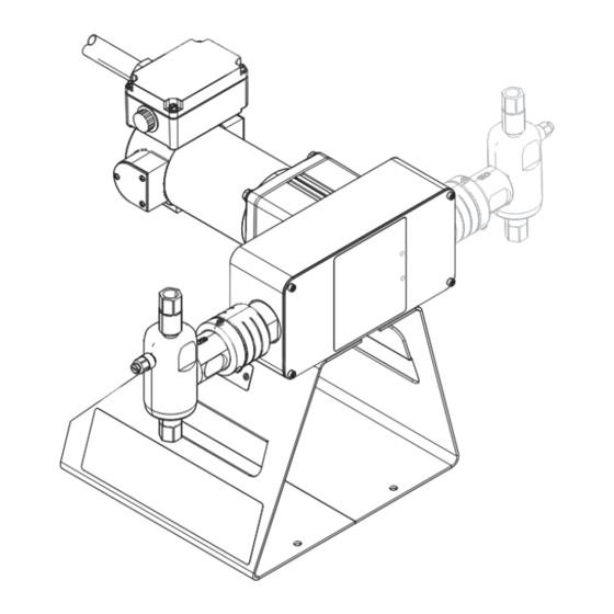
Component Identification Component Identification Wolverine Basic Wolverine Advanced . 1 Pump Components Numbered items in the key below correspond to the numbers in the Parts Lists starting on page 40. Key: Drive Housing Motor Motor Junction Box Motor Dust Cover End ring Drive Cylinder Pump Dust Cover... -
Page 19: Installation
Installation Installation Grounding The equipment must be grounded to reduce the risk of static sparking and electric shock. Electric or static sparking can cause fumes to ignite or explode. Improper grounding can cause electric shock. Grounding provides an escape wire for the electric current. -
Page 20: Typical Installation
Pump Control Box from what is shown here. The Wolverine pump (A) is the Solar Panel only component in F . 2 supplied by Graco. All other Stand Unit components are supplied by customer. Tank Pressure Relief Valve Inlet Line... -
Page 21: Choosing An Installation Location
3. Install a pressure relief valve (F) on the outlet side of the pump. NOTE: The pressure relief valve is available from Graco and can be connected back to the tank or directly to the inlet side of the pump. See Kits and Accessories on page 48. -
Page 22: Electrical Connections
Installation Electrical Connections For models A267xx and A297xx (3 Phase pumps) The pump assembly has nine motor leads housed inside the motor junction box (2a). See F . 1 on page To reduce the risk of electrical shock; • All electrical wiring must be done by a qualified 1. -
Page 23: Operation
Operation Operation Pressure Relief Procedure Flush the Equipment Follow the Pressure Relief Procedure whenever you see this symbol. This equipment stays pressurized until pressure is To avoid fire and explosion, always ground equipment manually relieved. To help prevent serious injury from and waste container. -
Page 24: Calibrate Chemical Dosage
Operation Calibrate Chemical Dosage Stroke Adjustment Wolverine Basic 1. Begin the process by setting the cycle rate and/or stroke adjustment of the pump to an estimated set- This pump has three defined stroke adjustment posi- ting for a desired flow rate. See Baseline Chemical tions. - Page 25 Operation 4. Reinstall spring pin (34) in desired stroke position. Wolverine Advanced This pump has infinite stroke adjustment positions between full stroke and half stroke. 1. Disconnect main power from pump. 2. Expose the drive shaft (33) by loosening the cap screws (27) and removing the drive guard (26).
- Page 26 Operation Baseline Chemical Dosage Settings See Stroke Adjustment, page 24, for stroke adjust settings. NOTE: Double values in the charts below for configurations with two pumps. 1/4 in. Fluid Plunger 3/8 in. Fluid Plunger 1/2 in. Fluid Plunger 5/8 in. Fluid Plunger 3/4 in.
-
Page 27: Preventive Maintenance Schedule
Operation Maintenance Preventive Maintenance Schedule The operating conditions of your particular pump deter- mines how often maintenance is required. Establish a preventive maintenance schedule by recording when and what kind of maintenance is needed, and then determine a regular schedule for checking your pump. Tighten Threaded Connections Check that all threaded connections are tight at routine intervals. -
Page 28: Troubleshooting
Troubleshooting Troubleshooting 1. Follow Pressure Relief Procedure, page 23, 2. Check all possible problems and causes before dis- before checking or repairing the pump. assembling the pump. Problem Cause Solution Air bubbles in fluid Suction line is loose Tighten Fluid leaking Loose fittings Tighten fittings Worn or damaged seals and/or pack-... -
Page 29: Repair
Repair Repair Wolverine Basic Pump Repair 3. Loosen, but do not remove, the packing nut (37). Disconnect Pump 1. Follow Pressure Relief Procedure, page 23. 2. Expose the packing nut (37) by rotating the dust cover (15) clockwise and sliding down when loose. . - Page 30 Repair 5. Rotate the cam (8) until the drive shaft (33) is all the 6. Remove the fluid cylinder (42) from the drive cylin- way down. der (14). . 10 Remove fluid cylinder from drive cylinder . 9 Rotate cam to depress drive shaft 334513A...
- Page 31 Repair 7. Disconnect the plunger (43) from the drive shaft (33) Pump Repair by sliding the head of the piston sideways out of the 1. Carefully remove plunger (43) from fluid cylinder slot in the bottom of the drive shaft, and pulling (42).
- Page 32 Repair 4. Replace packing (41) and bearings (39). Lubricate Reconnect Pump prior to reassembly. 1. Rotate the cam (8) until the drive shaft (33) is all the way down. . 14 Rotate cam to depress drive shaft 2. Connect the plunger (43) to the drive shaft (33) by pushing the plunger straight up before horizontally sliding the head of plunger into the slot at the bottom of the drive shaft.
- Page 33 Repair 3. Secure the fluid cylinder (42) to the drive cylinder 5. Cover the packing nut (37) by pushing up the dust (14) by pushing up on the fluid cylinder. Torque to cover (15) until the threads take hold. 30 ft-lbs (40 N•m). 4.
-
Page 34: Wolverine Advanced Pump Repair
Repair Wolverine Advanced Pump 3. Loosen, but do not remove, packing nut (37). Repair Disconnect Pump 1. Follow Pressure Relief Procedure, page 23. 2. Expose the packing nut (37) by loosening the dust cover (15) and sliding it towards the drive housing (1). - Page 35 Repair 5. Place two Allen wrenches (or similar tools) in the holes on the cam (8) and use them to rotate the cam until the key is towards the pump being repaired. . 20 Disconnect Wolverine Advanced Pump 6. Carefully remove the plunger (43) from the drive shaft (33).
- Page 36 Repair Pump Repair 3. Replace packing (41) and bearings (39). Inspect spacers and replace, if necessary. Lubricate prior to 1. Remove packing nut assembly from fluid cylinder reassembly. (42). . 23 Packing (41) detailed view Packing 4. Replace the o-ring (5) and back-up ring (6) on the Assembly outside of the packing nut (37).
- Page 37 Repair Reconnect Pump 5. Tighten packing nut assembly hand tight plus a 1/16th turn. 1. Reconnect the pump plunger (43) to the drive shaft (33). . 24 Reconnect plunger to drive shaft 2. While guiding the plunger (43) back into the fluid cylinder (42), guide the fluid cylinder into the drive cylinder (14).
-
Page 38: Motor Brush Repair (Dc Pumps Only)
Repair 9. Prime the Pump, page 23. Check Valve Repair 10. If necessary, Calibrate Chemical Dosage, page 11. Tighten packing nut as necessary to seal pump plunger. The following procedures apply to the check valves on both Wolverine Basic and Wolverine Advanced pumps. Motor Brush Repair (DC Pumps . - Page 39 Repair 12. Reconnect the inlet hose to the pump and reprime Outlet Check Valve the pump. 1. Follow the Pressure Relief Procedure on page 23. 2. Remove the outlet check valve assembly (25). 3. Remove the retaining nut (25d), spring (25e), and piston (25c).
-
Page 40: Parts
Parts Parts Wolverine Basic Pump Model A26000 shown 108▲ 107▲ 334513A... - Page 41 Parts Wolverine Basic Parts List Ref. Part Description Ref. Part Description Captive fastener, included with B32415 Motor & pump support molded guard (ref. 26) B32108 Motor B32083 Plunger return carriage Lock washer, included with B32408 Carriage bearing, included with motor (ref. 2) plunger return carriage (ref.
- Page 42 Parts Table 1: Packing Nut Part Numbers by Fluid Plunger Size Diameter 1/4 in. 3/8 in. 1/2 in. Qty. B32187 B32188 B32203 Table 2: Packing, including Plunger Bearings, qty 2 (ref. 39) Part Numbers by Fluid Plunger Size Diameter 1/4 in. 3/8 in.
-
Page 43: Wolverine Advanced Pump
Parts Wolverine Advanced Pump Model A26100 shown 108▲ 107▲ 334513A... - Page 44 Parts Wolverine Advanced Parts List Ref. Part Description Ref. Part Description B32410 Shoulder screw, included with B32416 Drive housing for small motor plunger return carriage (ref. 28) B32417 Drive housing for large motors & plunger return block (ref. 16) B32108 Motor: small, 12 VDC Set screw, included with drive B32109 Motor: large, 12 VDC cylinder (ref.
- Page 45 Parts Ref. Part Description Ref. Part Description B32403 Stroke adjuster Plunger Table 9 B32418 Stroke adjust nut Plug Packing nut Table 6 Pump base O-Ring, included with Flat washer Table 5 check/bleed housing (ref. 11) & Socket head cap screw &...
- Page 46 Parts Table 6: Packing Nut Part Numbers by Fluid Plunger Size Diameter 1/4 in. 3/8 in. 1/2 in. 5/8 in. 3/4 in. Qty. B32421 B32422 B32423 B32424 B32425 FKMETP B32490 B32491 B32492 B32493 B32494 HNBR B32497 B32498 B32499 B32500 B32501 FFKM B32504 B32505...
- Page 47 Parts Table 8: Fluid Cylinder Part Numbers by Fluid Plunger Size Diameter 1/4 in. 3/8 in. 1/2 in. 5/8 in. 3/4 in. Qty. B32483 B32484 B32485 B32486 B32487 FKMETP B32517 B32518 B32519 B32520 B32521 HNBR B32524 B32525 B32526 B32527 B32528 FFKM B32531 B32532...
-
Page 48: Kits And Accessories
Kits and Accessories Kits and Accessories Wolverine (Both) B32461 5/8" FKM ETP Fluid Section Conversion Kit* Part No. Description B32462 3/4" FKM ETP Fluid Section Conversion B32038 FKM Inlet and Outlet Check Valve Repair Kit* Kit (includes ref. 24b,25b,25e) B32463 1/8" HNBR Fluid Section Conversion Kit* B32039 FKM ETP Inlet and Outlet Check Valve B32464 3/16"... -
Page 49: Dimensions
Dimensions Dimensions Wolverine Basic Pump Dimensions . 28 Wolverine Basic Pump Dimensions 4.65 in. 7.35 in. 3.6 in. 11.5 in. 8.9 in. 8.0 in. 5.0 in. 0.281 in. dia (11.8 cm) (18.7 cm) (9.1 cm) (29.2 cm) (22.7 cm) (20.3 cm) (12.7 cm) (0.714 cm) 334513A... -
Page 50: Wolverine Advanced Pump Dimensions
Dimensions Wolverine Advanced Pump Dimensions . 29 Wolverine Advanced Pump Dimensions 15.65 in. 8.9 in. 4.5 in. 2.85 in. 11.9 in. 8.9 in. 8.0 in. 5.0 in. 0.281 in. dia (39.8 cm) (22.6 cm) (11.4 cm) (7.2 cm) (30.2 cm) (22.7 cm) (20.3 cm) (12.7 cm) -
Page 51: Technical Data
Technical Data Technical Data Wolverine Chemical Injection Pump Metric Maximum fluid working pressure Varies by model. See Models on page 3. Input Voltage CI-12X-XXX-XXX-X 12 VDC CI-1AX-XXX-XXX-X 115 VAC CI-2AX-XXX-XXX-X 230 VAC CI-4AX-XXX-XXX-X 230 VAC or 460 VAC 3 Phase Input Current CI-12S-XXX-XXX-X 11 A maximum (small motor) -
Page 52: Graco Standard Warranty
With the exception of any special, extended, or limited warranty published by Graco, Graco will, for a period of twelve months from the date of sale, repair or replace any part of the equipment determined by Graco to be defective.
Need help?
Do you have a question about the Wolverine Series and is the answer not in the manual?
Questions and answers