Table of Contents
Advertisement
Quick Links
Instructions/Parts
Merkur
and Airless
Spray Packages
Spray packages with a bellows seal for use with isocyanates, UV coatings and other
moisture-sensitive materials. For professional use only.
Important Safety Instructions
Read all warnings and instructions in this manual.
Save these instructions.
See pages 8-13 for model information, including maximum air inlet pressures and maximum fluid working pressures.
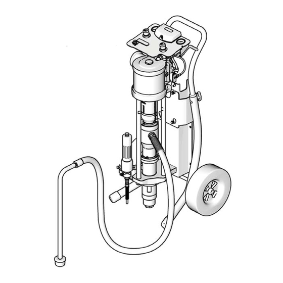
Cart Mount
™
Bellows AA
ti14530a
Australian Patent No. 2006275866
Chinese Patent Nos. ZL200680027833.0 and
ZL200680027760.5
European Community Patent No. 1910678
Russian Patent No. 2413096
Ukrainian Patent Nos. 59881, 89254 and 93051
United States Patent No. 8,066,491
Other patents pending
Wall Mount
312799H
ti15428b
II 2 G c IIB T3 (200°C)
EN
Advertisement
Table of Contents

Related Manuals for Graco Merkur Bellows


Summary of Contents for Graco Merkur Bellows
- Page 1 Instructions/Parts ™ Merkur Bellows AA and Airless 312799H Spray Packages Spray packages with a bellows seal for use with isocyanates, UV coatings and other moisture-sensitive materials. For professional use only. Australian Patent No. 2006275866 Important Safety Instructions Chinese Patent Nos. ZL200680027833.0 and Read all warnings and instructions in this manual.
-
Page 2: Table Of Contents
Flush the Pump Before First Use ... 18 Graco Information ......44 Trigger Lock . -
Page 3: Related Manuals
Related Manuals Related Manuals Manual Description 312793 Merkur Bellows Displacement Pump 312795 Merkur Bellows Pump Assembly 312796 ™ Air Motor 312798 Merkur Electrostatic Packages 3A0149 G15/G40 Spray Gun 312145 ™ ™ 5 and XTR 7 Airless Spray Gun 307273 Fluid Outlet Filter... -
Page 4: Warnings
Warnings Warnings The following warnings are for the setup, use, grounding, maintenance, and repair of this equipment. The exclama- tion point symbol alerts you to a general warning and the hazard symbols refer to procedure-specific risks. When these symbols appear in the body of this manual, refer back to these Warnings. Additional, product-specific warnings may be found throughout the body of this manual where applicable. - Page 5 Warnings WARNING WARNING WARNING WARNING EQUIPMENT MISUSE HAZARD Misuse can cause death or serious injury. • Do not operate the unit when fatigued or under the influence of drugs or alcohol. • Do not exceed the maximum working pressure or temperature rating of the lowest rated system com- ponent.
-
Page 6: Important Two-Component Material Information
Important Two-Component Material Information Important Two-Component Material Information Isocyanate Conditions Moisture Sensitivity of Isocyanates Isocyanates (ISO) are catalysts used in two component coatings. ISO will react with moisture (such as humidity) Spraying or dispensing materials containing isocya- to form small, hard, abrasive crystals, which become nates creates potentially harmful mists, vapors, and suspended in the fluid. -
Page 7: Models
Models Models Check the identification plate (ID) for the 6-digit part number of your package. Use the following matrix and tables to define the components of your package. For example, package number G15B54 represents a Merkur package (G), with a 15:1 ratio pump (15), bellows style (B), and the components shown for (54) in the table on page 9. ti15432a Second and Third Digits Fourth Digit... -
Page 8: 5:1 Packages (G05Bxx)
Models 5:1 Packages (G05Bxx) Maximum Inlet Air Pressure: 100 psi (0.7 MPa, 7 bar) Maximum Fluid Working Pressure: 500 psi (3.4 MPa, 34 bar) Model Air Controls Weight - lb/kg Maximum Pump Fluid Flow Wall Cart Pump Pump Fluid Data Rate Wall Cart... -
Page 9: 15:1 Packages (G15Bxx)
Models 15:1 Packages (G15Bxx) Maximum Inlet Air Pressure: 100 psi (0.7 MPa, 7 bar) Maximum Fluid Working Pressure: 1500 psi (10.3 MPa, 103 bar) Model Air Controls Hoses Accessories Weight - lb/kg Maximum Pump Fluid Flow Wall Cart Pump Pump Siphon Fluid Data... -
Page 10: 23:1 Packages (G23Bxx)
Models 23:1 Packages (G23Bxx) Maximum Inlet Air Pressure: 100 psi (0.7 MPa, 7 bar) Maximum Fluid Working Pressure: 2300 psi (15.9 MPa, 159 bar) Model Air Controls Hoses Accessories Weight - lb/kg Maximum Pump Fluid Flow Wall Cart Pump Pump Siphon Fluid Data... -
Page 11: 24:1 Packages (G24Bxx)
Models 24:1 Packages (G24Bxx) Maximum Inlet Air Pressure: 100 psi (0.7 MPa, 7 bar) Maximum Fluid Working Pressure: 2400 psi (16.5 MPa, 165 bar) Model Air Controls Hoses Accessories Weight - lb/kg Maximum Pump Fluid Flow Wall Cart Pump Pump Siphon Fluid Data... -
Page 12: 25:1 Packages (G25Bxx)
Models 25:1 Packages (G25Bxx) Maximum Inlet Air Pressure: 100 psi (0.7 MPa, 7 bar) Maximum Fluid Working Pressure: 2500 psi (17.2 MPa, 172 bar) Model Air Controls Hoses Accessories Weight - lb/kg Maximum Pump Fluid Flow Wall Cart Pump Pump Siphon Fluid Data... -
Page 13: 35:1 Packages(G35Bxx)
Models 35:1 Packages (G35Bxx) Maximum Inlet Air Pressure: 100 psi (0.7 MPa, 7 bar) Maximum Fluid Working Pressure: 3500 psi (24.1 MPa, 241 bar) Model Air Controls Hoses Accessories Weight - lb/kg Maximum Pump Fluid Flow Wall Cart Pump Pump Fluid Siphon Fluid... -
Page 14: Installation
. 1 and F . 2 are only guides for selecting and installing system components and accessories. Contact your Graco distributor for assistance in designing a sys- NOTE: Reference numbers and letters in parentheses in tem to suit your particular needs. -
Page 15: Prepare The Site
Installation Prepare the Site Keep the site clear of any obstacles or debris that could interfere with the operator's movement. Ensure that you have an adequate compressed air Have a grounded, metal pail available for use when supply. flushing the system. Bring a compressed air supply line from the air com- pressor to the pump location. -
Page 16: Mount The Pump
Mount the pump directly to the wall (order Wall Mounting Kit, page 37) or to a Graco cart (order Cart Mounting Kit • The air relief valve (not shown) opens automati- 24E879). -
Page 17: Air Line Accessories
Check electrical resistance of hose. If total resistance to ground exceeds 25 meg- ohms, replace hose immediately. Air compressor: follow manufacturer’s recommenda- tions. Spray gun / Dispense valve: Ground the spray gun through connection to a Graco-approved grounded fluid hose. 312799H... -
Page 18: Operation
Operation Operation Pressure Relief Procedure Flush the Pump Before First Use The pump is tested with lightweight oil, which is left in to protect the pump parts. If the fluid you are using may be contaminated by the oil, flush it out with a compatible solvent. -
Page 19: Prime And Adjust The Pump
Operation Prime and Adjust the Pump 8. Cycle pump slowly until all air is pushed out and the pump and hoses are fully primed. NOTICE 9. Pumps with runaway protection: Disable the prime/flush function by pushing the prime/flush but- TO PREVENT A BELLOWS FAILURE: ton on the DataTrak. -
Page 20: Adjust The Spray Pattern
Operation Adjust the Spray Pattern OUT (narrower pattern) IN (wider pattern) 1. Do not turn on atomizing air supply. Fluid pressure is controlled by the air pressure supplied to the pump (pump air regulator). Set fluid pressure at low starting pressure. For low viscosity fluids (less than 25 sec, #2 Zahn cup) with lower percent solids (typi- cally less than 40%), start at 300 psi (2.1 MPa, 21 bar) at pump outlet. -
Page 21: Shutdown
Maintenance Shutdown Flushing Read all Warnings. Follow all Grounding instructions. See page 17. Follow Pressure Relief Procedure, page 18. Flush the pump: Always flush the pump before the fluid dries on the dis- placement rod. See Flushing on page 21. •... -
Page 22: Datatrak Controls And Indicators
DataTrak Controls and Indicators DataTrak Controls and Indicators Key for F AA Runaway Limit, in cycles per minute (user settable; CF Cycle/Flow Rate 00=OFF) BT Batch Totalizer AB Lower Displacement (user settable) GT Grand Totalizer RT Runaway Toggle (enable/disable) /min, AC Flow Rate Units (user settable to gpm [US], gpm UT E1 Toggle... -
Page 23: Datatrak Operation
See page 25 for a description of E1, E2, and E5 error codes. NOTE: Graco recommends setting runaway to 60 All DataTrak modules are shipped with runaway monitor- ing not enabled. - Page 24 DataTrak Operation Prime/Flush Display 1. See F . 8. To enter Prime/Flush mode, press any See F . 8. The display (AE) will turn off after 1 minute of inactivity in Run mode or 3 minutes in Setup mode. key to wake up the display, then press .
- Page 25 DataTrak Operation Table 1: Diagnostic Codes Symbol Code Code Name Diagnosis Cause Runaway Pump running faster than set • Increased air pressure. runaway limit. • Increased fluid output. • Exhausted fluid supply. Diving Up Leak during upstroke. Worn piston valve or packings. Diving Down Leak during downstroke.
- Page 26 . 12. non-hazardous location. Use only the following approved replacement batter- Replace Fuse ies. Use of an unapproved battery will void Graco’s 1. Remove the screw, metal strap, and plastic holder. warranty and FM and Ex approvals. • Ultralife lithium # U9VL 2.
-
Page 27: Troubleshooting
Troubleshooting Troubleshooting NOTE: Check all possible problems and causes before disassembling the pump. Relieve the pressure, page 18, before checking or servicing the equipment. Problem Cause Solution Pump fails to operate. Restricted line or inadequate air sup- Clear line or increase air supply. Check ply;... -
Page 28: Parts
Parts Parts Cart Mount ti15429a 312799H... -
Page 29: Wall Mount
Parts Wall Mount ti15430b NOTE: Parts List • See page 37 for mounting kits for all packages. Package Page • See pages 36-42 for repair parts and accessories. G05Bxx G12Bxx G15Bxx G23Bxx G24Bxx G25Bxx G35Bxx 312799H... -
Page 30: G05Bxx Models
Parts G05Bxx Models G12Bxx Models This list includes all possible parts for G05Bxx pack- This list includes all possible parts for G12Bxx pack- ages. See page 8 to check whether a part is included in ages. See page 8 to check whether a part is included in your particular package. -
Page 31: G15Bxx Models
Parts G15Bxx Models This list includes all possible parts for G15Bxx packages. See page 9 to check whether a part is included in your par- ticular package. Part Description Part Description 17†◆ 111799 SCREW, M8 x 16; included with Part 28 Pump Assembly;... -
Page 32: G23Bxx Models
Parts G23Bxx Models This list includes all possible parts for G23Bxx packages. See page 10 to check whether a part is included in your particular package. Part Description Part Description 55‡ ----- MOUNTING WEDGE, left, air control Pump Assembly; see Manual 312795 panel, cart mount B23DA0 M12LN0 x LB100A 56‡... -
Page 33: G24Bxx Models
Parts G24Bxx Models This list includes all possible parts for G24Bxx packages. See page 11 to check whether a part is included in your particular package. Part Description Part Description 55‡ ----- MOUNTING WEDGE, left, air control Pump Assembly; see Manual 312795 panel, cart mount B24FA0 M18LN0 x LB150A 56‡... -
Page 34: G25Bxx Models
Parts G25Bxx Models This list includes all possible parts for G25Bxx packages. See page 12 to check whether a part is included in your particular package. Part Description Part Description ----- HOSE, drain; included with Part 43 Pump Assembly; see Manual 312795 512351 ADAPTER, fluid hose, 1/4-18 npt x B25BA0 M07LN0 x LB050A 3/8-18 npt;... -
Page 35: G35Bxx Models
Parts G35Bxx Models This list includes all possible parts for G35Bxx packages. See page 12 to check whether a part is included in your particular package. Part Description Part Description 55‡ ----- MOUNTING WEDGE, left, air control Pump Assembly; see Manual 312795 panel, cart mount B35DA0 M18LN0 x LB100A 56‡... -
Page 36: Kits
Kits Kits Cart Mounting Kit Ref. Part Description Qty. Kit 24E879 Includes the cart, mounting plate (30), and ----- CART, frame hardware for all pump sizes. Use to mount a bare pump ----- HANDLE, cart on a cart. See details in kit parts list to determine the 119451 WHEEL, semi-pneumatic hardware needed for your pump. -
Page 37: Wall Mounting Kit
Kits Wall Mounting Kit Air Control Mounting Kit-Wall Includes mounting plate (30) and hardware (see Mount- Kit 24E883 includes bracket (28), hex nuts (32), and ing Hardware Kits). Use to mount a bare pump on the screws (17). Use if adding air controls to a wall mount wall. -
Page 38: Pump And Gun Control Panel Kits
Kits Pump and Gun Control Panel Kits ti13565a ti13467a M07xxx, M12xxx, and M18xxx air motors M04xxx air motors Kits 24A581 Kit 24A585 Ref. Part Description Qty. Ref. Part Description Qty. 114362 VALVE, ball 114362 VALVE, ball 15T643 SWIVEL, tee, 3/8 npt(m) x 1/2T ----- SWIVEL, tee -----... -
Page 39: Pump Only Control Panel Kits
Kits Pump Only Control Panel Kits 307 308 ti13567a ti13566a M07xxx, M12xxx, and M18xxx air motors M04xxx air motors Kit 24A583 Kit 24A586 Ref. Part Description Qty. Ref. Part Description Qty. 301 114362 VALVE, ball 301 114362 VALVE, ball ----- TUBE, 1/2 OD, cut to fit, 1.5 ft. -
Page 40: Datatrak Kits
Kits DataTrak Kits DataTrak Conversion Kits Fits NXT Air Valve Air Motor Replacement Kit Part Description Models Required* DataTrak with M04LN0 24A353 24A575 Runaway M04LT0 ----- Protection Kit M07LN0– 24A354 DataTrak with M18LN0 24A576 Runaway M07LT0– Protection Kit ----- M18LT0 DataTrak with 24A592 Cycle Count... -
Page 41: Drain Valve Kit 256425
Kits Drain Valve Kit 256425 Includes drain valve (43), coupling (44), and hose (45). Overflow Chamber Kit 24E298 Includes overflow cup, with seals and necessary hard- ware. Reinforced PTFE V-Packing Kits and PTFE Bellows Kits NOTE: See manual 312793 for information related to optional kits with reinforced PTFE seals and optional kits with PTFE bellows. -
Page 42: Guns And Hoses
Kits Guns and Hoses G15 and G40 To find the correct parts for your model, locate the gun you have. The correct hoses and related parts are listed in the table below each gun. XTR 5 ti11993a Ref. Part Description Qty. -
Page 43: Mounting Plate Dimensions
Mounting Plate Dimensions Mounting Plate Dimensions 6.9 in. (175 mm) 2.167 in. (55 mm) 8.5 in. (216 mm) 17.0 in. (432 mm) 6 x 0.400 in. (10 mm) ti15369a Technical Data Maximum fluid working pressure ... . . See Models tables on pages 8-12. Maximum fluid inlet pressure . -
Page 44: Graco Standard Warranty
With the exception of any special, extended, or limited warranty published by Graco, Graco will, for a period of twelve months from the date of sale, repair or replace any part of the equipment determined by Graco to be defective.
Need help?
Do you have a question about the Merkur Bellows and is the answer not in the manual?
Questions and answers