Table of Contents
Advertisement
Quick Links
Instructions-Parts
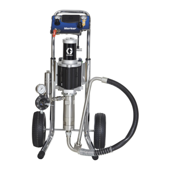
Merkur
Airspray Packages
For electrostatic finishing and coating applications in hazardous or non-hazardous
locations. For professional use only.
See pages 4 to 5 for model information, including
maximum working pressure and approvals.
Important Safety Instructions
Read all warnings and instructions in this
manual before using the equipment.
Save these instructions.
®
Electrostatic
3A7004B
EN
ti36765a
Advertisement
Table of Contents

Related Manuals for Graco Merkur


Summary of Contents for Graco Merkur
- Page 1 Instructions-Parts ® Merkur Electrostatic Airspray Packages 3A7004B For electrostatic finishing and coating applications in hazardous or non-hazardous locations. For professional use only. See pages 4 to 5 for model information, including maximum working pressure and approvals. Important Safety Instructions Read all warnings and instructions in this manual before using the equipment.
-
Page 2: Table Of Contents
Graco Standard Warranty ....32 Graco Information......32... -
Page 3: Related Manuals
Related Manuals Related Manuals Manual Description 312792 Merkur® Displacement Pump 312794 Merkur® Pump Assembly 312796 NXT® Air Motor 3A2494 ™ Pro Xp Electrostatic Air Spray Gun 307273 Fluid Outlet Filter 313541 DataTrak Kits 3A7004B... -
Page 4: Models
Check the identification plate (ID) for the 6-digit part number of your package. Use the following matrix and tables to define the components of your package. For example, package number G03C10 represents a Merkur package (G), with a 3:1 ratio pump (03), cart mounting (C), and the components shown for (10) in the table on page 5. -
Page 5: Merkur 3:1 Packages
Models Merkur 3:1 Packages (G03Wxx and G03Cxx) Maximum Inlet Air Pressure 50 psi (.34 MPa, 3.4 bar) Maximum Fluid Working Pressure: 120 psi (.83 MPa, 8.3 bar) Model Air Controls Hoses Accessories Fluid Fluid Gun Air Reg. Pump Hose Hose... -
Page 6: Warnings
Ground all equipment, personnel, object being sprayed, and conductive objects in or close to spray area. Resistance must not exceed 1 megohm. See Grounding instructions. • Only use grounded Graco conductive air supply hoses. • Do not use pail liners unless they are conductive and grounded. - Page 7 Models WARNING EQUIPMENT MISUSE HAZARD Misuse can cause death or serious injury. • Do not operate the unit when fatigued or under the influence of drugs or alcohol. • Do not exceed the maximum working pressure or temperature rating of the lowest rated system component.
- Page 8 Models WARNING PERSONAL PROTECTIVE EQUIPMENT Wear appropriate protective equipment when in the work area to help prevent serious injury, including eye injury, hearing loss, inhalation of toxic fumes, and burns. Protective equipment includes but is not limited to: • Protective eyewear, and hearing protection. •...
-
Page 9: Installation
Typical Installation Typical Installation Package components vary. See page 24 to determine the components included in your model. Any item designated as required is not included in the packages but is necessary for operation. V or Y ti36766 . 1. Typical Installation Key: Air Shutoff Valve (required) Gun Air Pressure Regulator... -
Page 10: General Information
Graco distributor. If you supply your own accessories, be sure they are adequately Mount the pump directly to the wall or to a Graco cart. sized and pressure-rated for your system. See page 27 for mounting kits. -
Page 11: Components
• DataTrak (V) provides pump diagnostics and mate- Electrostatic Spray Gun: Use only the Graco Electri- rial usage information. See page 17. cally Conductive Air Supply Hose (supplied). Connect the Gun Grounding Wire (AC) to the ground screw (GS) on the air motor. -
Page 12: Setup
Typical Installation All electrically conductive objects or devices in the Setup spray area, including paint containers, wash cans and tools, must be properly grounded. 1. See F . 1. Attach the gun fluid hose (Z) to the fluid regulator (G) outlet. All persons entering 2. -
Page 13: Operation
Operation Operation 2. Close the bleed-type master air valve (U). 3. Trigger the gun into a grounded metal waste con- tainer to relieve pressure. When operating the electrostatic gun, any ungrounded objects in the spray area (people, 4. Open all fluid drain valves in the system, having a containers, tools, etc.) can become electrically waste container ready to catch drainage. -
Page 14: Wet Cup
9. Cycle pump slowly until all air is pushed out and Before starting, fill wet cup 1/3 full with Graco Throat pump and hoses are fully primed. Seal Liquid (TSL) or compatible solvent. -
Page 15: Maintenance
11. Clean the inside and outside of the suction tube. Flush the pump: Wet Cup • Before first use Fill the wet cup 1/3 full with Graco Throat Seal Liquid • When changing colors or fluids (TSL). Maintain level daily. •... -
Page 16: Troubleshooting
Fluid dried on the displacement rod. Clean; always stop the pump at the bottom of its stroke; keep the wet-cup 1/3 filled with Graco throat seal liquid (TSL). Dirty, worn, or damaged air motor Clean or repair air motor. See NXT Air Motor parts. -
Page 17: Datatrak Controls And Indicators
DataTrak Controls and Indicators DataTrak Controls and Indicators Key for F AA Runaway Limit, in cycles per minute (user settable; RK Reset Key (Resets faults. Press and hold for 3 seconds to 00=OFF) clear the batch totalizer.) Push to toggle between flow rate AB Lower Displacement (user settable) and cycle rate. -
Page 18: Datatrak Operation
See page 20 for a descrip- tion of E1, E2, and E5 error codes. NOTE: Graco recommends setting runaway (if equipped) to 60 . All DataTrak modules are shipped with runaway protection not enabled. - Page 19 DataTrak Operation Prime/Flush Diagnostics 1. See F . 4. To enter Prime/Flush mode, press any DataTrak can diagnose several problems with the pump. When the monitor detects a problem, the LED (AD, F key to wake up the display, then press .
- Page 20 DataTrak Operation Table 1: Diagnostic Codes Symbol Code Code Name Diagnosis Cause • Runaway Pump running faster than set Increased air pressure. (DataTrak only) runaway limit. • Increased fluid output. • Exhausted fluid supply. 3A7004B...
- Page 21 DataTrak Operation Table 1: Diagnostic Codes Symbol Code Code Name Diagnosis Cause Diving Up Leak during upstroke. Worn piston valve or packings. Diving Down Leak during downstroke. Worn intake valve. Low Battery Battery voltage too low to stop Low battery. Replace battery; runaway.
-
Page 22: Replace Datatrak Battery Or Fuse
ABLE ABLE Ultralife® brand lithium # U9VL Use of an unapproved battery or fuse will void Graco’s warranty and Intertek and Ex approvals. Duracell® brand alkaline # MN1604 Replace Battery 1. Unscrew cable from the back of the reed switch assembly. - Page 23 3. Replace with an approved fuse from Table 3. 24C580 All other part numbers B and later 24V216 . 8 shows where to find the Series letter. ‡ Graco Part Numbers Solenoid Cable Connection Fuse Screw, Metal Strap, Plastic Holder...
-
Page 24: Parts
Parts Parts Cart Mount ti36768 ti36767c 3A7004B... -
Page 25: Wall Mount
Parts Wall Mount ti36768 ti36767 3A7004B... -
Page 26: Parts
Parts Parts Part Description Part Description 105332 NUT, lock, M5 x 0.08 (included with ASSEMBLY, pump Part 49) W03EAS G03W11, G03W13, G03W17, G03W19, G03C11, and G03C13 19A605 BRACKET, air controls, wall mount W03EBS G03W10, G03W12, G0C10, and units G03C12 116940 SCREW, cap, sh, 5/16-18, wall mount 24E459 PANEL, air control, see page 28... -
Page 27: Kits
Kits Kits Wall Mount Kit 24A578 (non-Bellows) Ref. Description SCREW, cap, M8 x 1.25 PLATE, wall mount ti12633a Cart Mount Kit 256427 (non-Bellows) Ref. Part Description ----- CART, frame ----- HANDLE, cart 119451 WHEEL, semi-pneumatic 119452 CAP, hub ----- SLEEVE, cart handle 15C871 CAP, leg 115480... -
Page 28: Pump And Gun Control Panel Kits
Kits Pump and Gun Control Panel Kits ti13467a ti13565b Kit 24A581 and Kit 24A584 Ref. Part Description Ref. Part Description 313 15T538 NUT, regulator 314 114381 SCREW, cap, button head 301 114362 VALVE, ball 315 15T539 REGULATOR, air, gun, 3/8 npt 302 15T643 SWIVEL, tee, 3/8 npt(m) x 1/2T 316 116514 NUT, regulator 303 -----... -
Page 29: Air Controls Mounting Kit (Non-Bellows)
Kits Air Controls Mounting Kit (non-Bellows) Includes one mounting bracket (49), two lock nuts (16), and two hex head screws (51). Packages Air Controls Mounting Kit, Wall Mount 24E883 DataTrak NOTE: See DataTrak manual, 313541, for all DataTrak related part numbers and kit information, including the reed switch and solenoid. -
Page 30: Mounting Dimensions
Mounting Dimensions Mounting Dimensions Wall Bracket (Non-Bellows) 11 in. (279 mm) 4 in. (102 mm) ti12833a Four 0.40 in. (10 mm) mounting holes 3A7004B... -
Page 31: Technical Specifications
49°C Sound Data See Technical Data in air motor manual 312796. Wetted Parts (displacement pump) See manual 312792 (Merkur) or 312793 (Merkur Bellows). Wetted Parts (spray gun) See manual 3A2494 (Pro Xp Electrostatic Air Spray Gun). Wetted Parts (fluid hoses) -
Page 32: Graco Standard Warranty
With the exception of any special, extended, or limited warranty published by Graco, Graco will, for a period of twelve months from the date of sale, repair or replace any part of the equipment determined by Graco to be defective.
Need help?
Do you have a question about the Merkur and is the answer not in the manual?
Questions and answers