Table of Contents
Advertisement
Quick Links
Instructions-Parts
Wolverine
Chemical Injection
Pump
Electric pump for injecting chemicals at well sites. For professional use only.
Not approved for use in explosive atmospheres or hazardous locations unless otherwise
stated in the model approvals section.
See page 3 for model information, including maximum working pressure.
Important Safety Instructions
Read all warnings and instructions in this manual.
Save all instructions.
Wolverine Advanced
™
334513E
Wolverine Basic
EN
Advertisement
Table of Contents

Subscribe to Our Youtube Channel
Related Manuals for Graco Wolverine Advanced


Summary of Contents for Graco Wolverine Advanced
- Page 1 Not approved for use in explosive atmospheres or hazardous locations unless otherwise stated in the model approvals section. See page 3 for model information, including maximum working pressure. Important Safety Instructions Read all warnings and instructions in this manual. Save all instructions. Wolverine Advanced Wolverine Basic...
-
Page 2: Table Of Contents
Flush the Equipment ..... 22 Graco Standard Warranty ....66 Prime the Pump . -
Page 3: Models And Approvals
1500 (10.3, 103) 1/2 in. 800 (5.5, 55) A260xx 12 VDC Small Not approved for use in Euro- pean explosive atmospheres or hazardous locations Wolverine Advanced Pumps Maximum Working Pressure Models Voltage Motor Plunger Size psi (MPa, bar) Approvals 3/16 in. -
Page 4: Wolverine Hazardous Location Pumps
Models and Approvals Maximum Working Pressure Models Voltage Motor Plunger Size psi (MPa, bar) Approvals 3/16 in. 10,000 (69.0, 690) 1/4 in. 6000 (41.3, 413) 3/8 in. 2500 (17.2, 172) A267xx 230/460 VAC Large A297xx 3 Phase 1/2 in. 1250 (8.6, 86) Not approved for use in Euro- 5/8 in. -
Page 5: Fluid Modules
Models and Approvals Fluid Modules Maximum Working Pressure Plunger Size psi (MPa, bar) Approvals 3/16 in. 10,000 (69, 690) 1/4 in. 6000 (41.3, 413) 3/8 in. 2500 (17.2, 172) 1/2 in. 1250 (8.6, 86) 5/8 in. 900 (6.2, 62) 3/4 in. 600 (4.1, 41) 334513E... -
Page 6: Drive Modules
Models and Approvals Drive Modules Wolverine Advanced Drive Modules Drive Configuration Voltage Motor Approvals CI-12S-xx-x 12 VDC Small CI-12L-xx-x 12 VDC Large CI-1AL-xx-x 115 VAC Large CI-2AL-xx-x 230 VAC Large Not approved for use in Euro- CI-2AL-xx-x 230 VAC Large... -
Page 7: Wolverine Assembly Configuration Code
CI-12S-3XD-3XD-C ######## 1500 ( 10.3 ) 1500 ( 10.3 ) # #### Graco Inc., P.O. Box 1441 Mpls, MN 55440 USA Date Code . 1 Example of the Wolverine Assembly Identification Plate NOTE: Not all combinations are possible. Wolverine Assembly Configuration Code... -
Page 8: Drive Module Configuration Code
Drive Module Configuration Code Configuration Number Model Number A30002 CI-12S-57-0 ######## # #### Graco Inc., P.O. Box 1441 Mpls, MN 55440 USA Date Code . 2 Example of the Drive Module Identification Plate Sample Configuration Number: CI-12S-57-0 Chemical Injection Voltage Motor... -
Page 9: Fluid Module Configuration Code
Model Number A30600 CI-50-XA-0 ######## 1250 ( 8.6 ) # #### Graco Inc., P.O. Box 1441 Mpls, MN 55440 USA Date Code . 3 Example of the Fluid Module Identification Plate Sample Configuration Number: CI-50-XA-0 Chemical Injection Plunger Size Plunger Coating... -
Page 10: Key Points
• Continuous injection motors are large motors that do not require a controller for operation. They feature an integral variable speed controller and are adjustable from 0-67 Wolverine Advanced cpm. • Advanced pumps are higher-quality, modular, and more easily serviceable pumps available in numerous configu- Motors rations. -
Page 11: Warnings
Warnings Warnings The following warnings are for the setup, use, grounding, maintenance, and repair of this equipment. The exclama- tion point symbol alerts you to a general warning and the hazard symbols refer to procedure-specific risks. When these symbols appear in the body of this manual or on warning labels, refer back to these Warnings. Product-specific hazard symbols and warnings not covered in this section may appear throughout the body of this manual where applicable. - Page 12 Warnings MOVING PARTS HAZARD Moving parts can pinch, cut or amputate fingers and other body parts. • Keep clear of moving parts. • Do not operate equipment with protective guards or covers removed. • Pressurized equipment can start without warning. Before checking, moving, or servicing equipment, follow the Pressure Relief Procedure and disconnect all power sources.
-
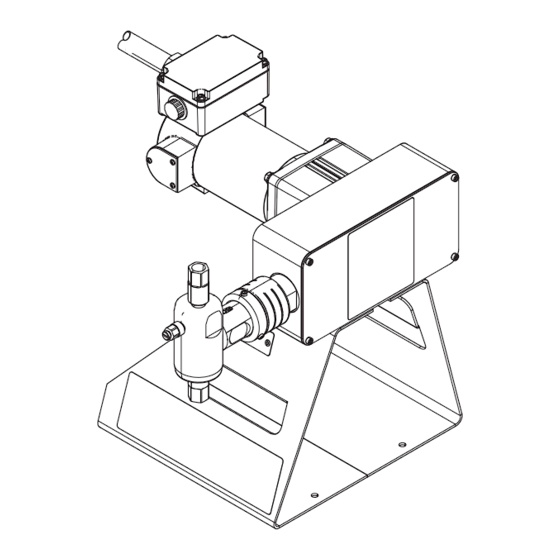
Page 13: Component Identification
Component Identification Component Identification Wolverine Basic Wolverine Advanced Wolverine Continuous Injection Wolverine Hazardous Location . 4 Pump Components 334513E... - Page 14 Key: Drive Housing Motor Motor Junction Box Motor Dust Cover End ring Control Box (Wolverine Continuous Injection only) Check Valve Housing (Wolverine Advanced and Hazardous Location only) Drive Cylinder Pump Dust Cover Prime/Bleed Valve Inlet Check Valve Outlet Check Valve...
-
Page 15: Installation
Installation Installation Grounding The equipment must be grounded to reduce the risk of static sparking and electric shock. Electric or static sparking can cause fumes to ignite or explode. Improper grounding can cause electric shock. Grounding provides an escape wire for the electric current. -
Page 16: Typical Installation - Ordinary Locations
(See Accessories on page Tank 15.) The Wolverine pump (A) is the only component in Pressure Relief Valve . 5 supplied by Graco. All other components are sup- Inlet Line plied by customer. Outlet Line... -
Page 17: Typical Installation - Hazardous Locations
(See Tank Accessories on page 15.) The Wolverine pump (A) is Pressure Relief Valve the only component in F . 6 supplied by Graco. All Inlet Line other components are supplied by customer. Outlet Line Pressure Relief Line... -
Page 18: Choosing An Installation Location
Protection Configuration Minimum Voltage Rating NOTE: A pressure relief valve is available from Graco and can be connected back to the tank or directly to the CI-12S-xx-x 12 VDC 15 A inlet side of the pump. See Kits and Accessories on... - Page 19 Installation Cycle Counter (models CI-xxS-xxx-xx-C For AC 3 Phase (model CI-4AL) and CI-xxL-xxx-xx-C only) The pump assembly has nine motor leads housed inside the motor junction box (2a). See F . 4 on page 1. Connect the harness wires (95) to the appropriate terminals.
- Page 20 Installation For Hazardous Location (models CI-xxH) 230 V / 3 Phase (Low Voltage) The pump assembly has motor leads housed inside the LINE 1 motor junction box (2a). See F . 4 on page 13. 1. Connect wires and related conduit (user supplied) LINE 2 MOTOR rated per local electrical code.
-
Page 21: Second Pump Add-On
Installation Second Pump Add-On 1. Follow Pressure Relief Procedure, page 22. . 10 2. Remove the drive guard (26). 3. Remove the plug (44) on the side of the housing (1) opposite of the existing pump. 4. Remove the two shoulder screws (17), and then remove the plunger return block (16). -
Page 22: Operation
Operation Operation Pressure Relief Procedure Flush the Equipment Follow the Pressure Relief Procedure whenever you see this symbol. This equipment stays pressurized until pressure is To avoid fire and explosion, always ground equipment manually relieved. To help prevent serious injury from and waste container. -
Page 23: Calibrate Chemical Dosage
Operation Calibrate Chemical Dosage Stroke Adjustment 1. Begin the process by setting the cycle rate and/or stroke adjustment of the pump to an estimated set- Wolverine Basic ting for a desired flow rate. See Baseline Chemical This pump has three defined stroke adjustment posi- Dosage Settings, page 25, for tables of cycles per tions. - Page 24 Full (1”, 25 mm) . 12 Wolverine Basic stroke adjustment positions 5. Reassemble the molded guard (26) to pump. . 13 Wolverine Advanced and Hazardous Location stroke adjustment 4. Reassemble the drive guard (26) to pump. 334513E...
- Page 25 Operation Baseline Chemical Dosage Settings See Stroke Adjustment, page 23, for stroke adjust settings. CPM (cycles per minute) is determined by controller settings for On/Off Time, or Cycles if using a Harrier-family chemical injection controller. Adjust the controller settings to change the CPM. Motor speed is also affected by voltage and back pressure. To use these charts, find the flow rate above the desired injection rate for the correct-sized plunger.
-
Page 26: Preventive Maintenance Schedule
Operation Maintenance Preventive Maintenance Schedule The operating conditions of your particular pump deter- mines how often maintenance is required. Establish a preventive maintenance schedule by recording when and what kind of maintenance is needed, and then determine a regular schedule for checking your pump. Tighten Threaded Connections Check that all threaded connections are tight at routine intervals. -
Page 27: Troubleshooting
Troubleshooting Troubleshooting 1. Follow Pressure Relief Procedure, page 22, 2. Check all possible problems and causes before dis- before checking or repairing the pump. assembling the pump. Problem Cause Solution Air bubbles in fluid Suction line is loose Tighten Fluid leaking Loose fittings Tighten fittings Worn or damaged seals and/or pack-... -
Page 28: Repair
Repair Repair Wolverine Basic Pump Repair 3. Loosen, but do not remove, the packing nut (37). Disconnect Pump 1. Follow Pressure Relief Procedure, page 22. 2. Expose the packing nut (37) by rotating the dust cover (15) and sliding down when loose. . - Page 29 Repair 5. Rotate the cam (8) until the drive shaft (33) is all the 6. Remove the fluid cylinder (42) from the drive cylin- way down. der (14). . 17 Remove fluid cylinder from drive cylinder . 16 Rotate cam to depress drive shaft 334513E...
- Page 30 Repair 7. Disconnect the plunger (43) from the drive shaft (33) Packing Repair by sliding the head of the piston sideways out of the 1. Carefully remove plunger (43) from fluid cylinder slot in the bottom of the drive shaft, and pulling (42).
- Page 31 Repair 4. Replace packing (41) and bearings (39). Lubricate Reconnect Pump prior to reassembly. 1. Rotate the cam (8) until the drive shaft (33) is all the way down. Gray Gray Gray . 21 Rotate cam to depress drive shaft Black 2.
- Page 32 Repair 3. Secure the fluid cylinder (42) to the drive cylinder 5. Cover the packing nut (37) by pushing up the dust (14) by pushing up on the fluid cylinder. Torque to cover (15) until the threads take hold. 30 ft-lbs (40 N•m). 4.
-
Page 33: Wolverine Advanced, Hazardous Location, And Continuous Injection Pump Repair
Repair Wolverine Advanced, Hazardous Location, and Continuous Injection Pump Repair Disconnect Pump 1. Follow Pressure Relief Procedure, page 22. 3. Loosen, but do not remove, packing nut (37). 2. Expose the packing nut (37) by loosening the dust cover (15) and sliding it towards the drive housing (1). - Page 34 Repair . 27 Disconnect Wolverine Advanced and Hazardous Location Pump 6. Carefully remove the plunger (43) from the drive shaft (33). . 28 Disconnect plunger from drive shaft 334513E...
- Page 35 4. Replace the o-ring (5) and back-up ring (6) on the outside of the packing nut (37). Lubricate prior to reassembly. . 29 Wolverine Advanced and Hazardous 5. Replace packing nut assembly into fluid cylinder. Location Pump Repair Tighten hand tight and back off 1/2 of a turn to pre- vent damage to packing during reassembly.
- Page 36 Repair Drive Section Repair Reconnect Pump 1. Disconnect Pump, page 28. 1. Reconnect the pump plunger (43) to the drive shaft (33). 2. Loosen and remove the drive cylinder (14) and dust cover (15) from the cylinder screw (31). 3. Loosen both stroke adjust nuts (36). 4.
-
Page 37: Dc Motor Brush Repair (Not Hazardous Location)
Repair 6. Cover the packing nut (37) by pushing up the dust DC Motor Brush Repair (not cover (15). Hazardous Location) 1. Disconnect pump from power source. 2. Remove dust cover screws and dust cover (2b) and o-ring. See F . -
Page 38: Check Valve Repair
(24c). Hazardous Location pumps. F . 35 shows the place- ment of the check valves on a Wolverine Advanced 5. Inspect parts for wear, and replace as needed. pump. On a Wolverine Basic pump, the outlet check valve (25), is on the side of the fluid cylinder. -
Page 39: Parts
Parts Parts Wolverine Basic Pump Model CI-12S-2XA-B00-0 shown 108 107 334513E... - Page 40 Parts Wolverine Basic Parts List Ref. Part Description Ref. Part Description B32408 Carriage bearing, included with B32415 Motor & pump support plunger return carriage (ref. 28) B32108 Motor Screw, included with drive cylinder Lock washer, included with motor (ref. 14) (ref.
- Page 41 Parts Table 1: Packing Nut Part Numbers by Fluid Plunger Size Diameter 1/4 in. 3/8 in. 1/2 in. Qty. B32187 B32188 B32203 Table 2: Packing, including Plunger Bearings, qty 2 (ref. 39) Part Numbers by Fluid Plunger Size Diameter 1/4 in. 3/8 in.
-
Page 42: Wolverine Advanced Pump
Parts Wolverine Advanced Pump Model CI-12L-xxx-xxx-C shown ‡ 108 6‡ 37‡ 5‡ 39‡ 40‡ 39‡ 25‡ 41‡ 23‡ 38‡ 22‡ 40‡ 42‡ 11‡ 43‡ 24‡ 20‡ 21‡ 107 334513E... - Page 43 Parts Wolverine Advanced Parts List Ref. Part Description Ref. Part Description Set screw, included with drive cylin- B32416 Drive housing for small motor der (ref. 14) & fluid cylinder (ref. 42) B32417 Drive housing for large motors 20‡ B32191 Bleed housing...
- Page 44 Parts Ref. Part Description 42‡ Fluid cylinder Table 8 43‡ Plunger Table 9 Plug Pump base Flat washer Socket head cap screw Liquid-tight flex metal conduit 91† 90-degree liquid-tight conduit con- nector 92† Liquid-tight conduit connector 93† Liquid-tight flex metal conduit 94†...
-
Page 45: Wolverine Hazardous Location Pump
Parts Wolverine Hazardous Location Pump Model CI-3AH-xxx-xxx-0 shown *Junction box only included with motor on models 3AH and 4AH ‡ 6‡ 37‡ 108 5‡ 40‡ 39‡ 25‡ 39‡ 23‡ 41‡ 38‡ 22‡ 42‡ 40‡ 11‡ 43‡ 20‡ 24‡ 21‡ 107 334513E... - Page 46 Parts Wolverine Hazardous Location Parts List Ref. Part Description Ref. Part Description 23‡ Ball retainer, included with B32537 Drive housing check/bleed housing (ref 11) B32149 Motor: 12 VDC, 1/5 HP 24‡ Inlet check valve B32209 Motor: 115/230 VAC, 1/4 HP Table 10 B32210 Motor: 230/460 VAC, 1/4 HP...
- Page 47 Parts Ref. Part Description 107 17G318 Multiple warning safety label 108 15H108 Pinch hazard warning label Pump Assembly ID label Fluid Module ID label (not shown; on Check/Bleed Housing, ref. 11) Drive Module ID label (not shown; opposite from Pump Assembly ID label, ref.
-
Page 48: Wolverine Continuous Injection Pump
Parts Wolverine Continuous Injection Pump Model CI-12B-xx-x shown ‡ 108 (includes control box) 6‡ 37‡ 5‡ 39‡ 40‡ 39‡ 25‡ 41‡ 23‡ 38‡ 22‡ 40‡ 42‡ 11‡ 43‡ 24‡ 20‡ 21‡ 107 334513E... - Page 49 Parts Wolverine Continuous Injection Parts List Ref. Part Description Ref. Part Description 21‡ Bleed valve, included with bleed B32416 Drive housing for small motor housing (ref. 20) B32417 Drive housing for large motors 22‡ Ball, included with check/bleed B32032 Motor: continuous injection, brush- housing (ref 11) less, 12 VDC 23‡...
- Page 50 Parts Ref. Part Description Replacement Danger and Warning labels, tags, and Plug cards are available at no cost. Pump base † Included in Cycle Counter kit, see Kits and Acces- Flat washer sories, page 53. Socket head cap screw ‡...
- Page 51 Parts Table 7: Packing, including Plunger Bearing, qty 2 (ref. 39) Part Numbers by Fluid Plunger Size Diameter 3/16 in. 1/4 in. 3/8 in. 1/2 in. 5/8 in. 3/4 in. Qty. B32429 B32430 B32431 B32432 B32433 B32434 FKMETP B32436 B32437 B32438 B32439 B32440...
- Page 52 Parts Table 10: Inlet Check Valve Part Numbers by Fluid Plunger Size Diameter 3/16 in. 1/4 in. 3/8 in. 1/2 in. 5/8 in. 3/4 in. Qty. B32216 B32024 B32024 B32024 B32024 B32024 FKMETP B32218 B32026 B32026 B32026 B32026 B32026 HNBR B32220 B32028 B32028...
-
Page 53: Kits And Accessories
(includes ref. 24b, 25b, 25e) B32157 316 SST Ball Valve Kit, 3/4 NPT (F) B32075 Electric Motor Brush Repair Kit (not Hazardous Location) Wolverine Advanced, Hazardous Location, and Continuous Injection A30503 3/8” FFKM: Chromex Fluid Module Part No. Description A30510 3/8”... - Page 54 Kits and Accessories A30800 3/4” FKM: Chromex Fluid Module A30801 3/4” FKM ETP: Chromex Fluid Module A30802 3/4” HNBR: Chromex Fluid Module A30803 3/4” FFKM: Chromex Fluid Module A30810 3/4” FKM: Ceramic Fluid Module A30811 3/4” FKM ETP: Ceramic Fluid Module A30812 3/4”...
-
Page 55: Dimensions
Dimensions Dimensions Wolverine Basic Pump Dimensions . 36 Wolverine Basic Pump Dimensions 4.65 in. 7.35 in. 3.6 in. 11.5 in. 8.9 in. 8.0 in. 5.0 in. 0.281 in. dia (11.8 cm) (18.7 cm) (9.1 cm) (29.2 cm) (22.7 cm) (20.3 cm) (12.7 cm) (0.714 cm) 334513E... -
Page 56: Wolverine Advanced Pump Dimensions
Dimensions Wolverine Advanced Pump Dimensions . 37 Wolverine Advanced Pump Dimensions 16.3 in. 8.9 in. 4.5 in. 2.85 in. 11.9 in. 8.9 in. 8.0 in. 5.0 in. 0.281 in. dia 23.7 in. (41.4 cm) (22.6 cm) (11.4 cm) (7.2 cm) (30.2 cm) -
Page 57: Wolverine Hazardous Location Pump Dimensions
Dimensions Wolverine Hazardous Location Pump Dimensions . 38 Wolverine Hazardous Location Pump Dimensions 16.3 in. 8.9 in. 4.5 in. 2.85 in. 19.6 in. 9.6 in. 7.5 in. 5.0 in. 0.281 in. dia 23.7 in. 19.6 in. Pump (41.4 cm) (22.6 cm) (11.4 cm) (7.2 cm) (49.8 cm) -
Page 58: Wolverine Continuous Injection Pump Dimensions
Dimensions Wolverine Continuous Injection Pump Dimensions . 39 Wolverine Continuous Injection Pump Dimensions 16.3 in. 8.9 in. 4.5 in. 2.85 in. 10.8 in. 8.9 in. 8.0 in. 5.0 in. 0.281 in. dia 23.7 in. (41.4 cm) (22.6 cm) (11.4 cm) (7.2 cm) (27.3 cm) (22.7 cm) -
Page 59: Performance Charts
Dimensions Performance Charts Wolverine Basic and Advanced Pumps 3/16 Inch Plunger (83) (76) (68) (61) (53) B-DC Advanced Simplex* (45) C-DC Advanced Duplex* (LPD) (38) D-AC Advanced Simplex* (30) E-AC Advanced Duplex* (23) *-Including Continuous Injec- (15) tion drives 1000 2000 3000 4000... - Page 60 Dimensions 3/8 Inch Plunger (341) (303) (265) A-DC Basic (227) B-DC Advanced Simplex* (189) (LPD) C-DC Advanced Duplex* (151) D-AC Advanced Simplex* E-AC Advanced Duplex* (114) *-Including Continuous Injec- (76) tion drives (38) 1000 1500 2000 2500 (3.45) (6.90) (10.34) (13.79) (17.24) (34.5)
- Page 61 Dimensions 5/8 Inch Plunger (1060) 280 (984) 260 (909) 240 (833) 220 (757) 200 (681) 180 B-DC Advanced Simplex* (606) 160 C-DC Advanced Duplex* (LPD) (530) 140 D-AC Advanced Simplex* (454) 120 E-AC Advanced Duplex* (379) 100 *-Including Continuous In- (303) 80 jection drives (227) 60...
- Page 62 Dimensions Wolverine Hazardous Location Pumps 3/16 Inch Plunger (68) (61) (53) (45) (38) A-Hazardous Location Simplex (LPD) B-Hazardous Location Duplex (30) (23) (15) 1000 2000 3000 4000 5000 6000 7000 8000 9000 10000 (6.90) (13.79) (20.68) (27.58) (34.47) (41.37) (48.26) (55.16) (62.05) (68.95)
- Page 63 Dimensions 3/8 Inch Plunger (341) (303) (265) (227) (189) (LPD) A-Hazardous Location Simplex B-Hazardous Location Duplex (151) (114) (76) (38) 1000 1500 2000 2500 (3.45) (6.90) (10.34) (13.79) (17.24) (34.5) (69.0) (103.4) (137.9) (172.4) PSI (MPa, Bar) . 48 1/2 Inch Plunger (568) 150 (530) 140 (492) 130...
- Page 64 Dimensions 5/8 Inch Plunger (833) (757) (681) (606) (530) (454) (LPD) A-Hazardous Location Simplex B-Hazardous Location Duplex (379) (303) (227) (151) (76) 1000 (1.38) (2.76) (4.14) (5.52) (6.90) (13.8) (27.6) (41.4) (55.2) (69.0) PSI (MPa, Bar) . 50 3/4 Inch Plunger (1211) 320 (1136) 300 (1060) 280...
-
Page 65: Technical Data
Wolverine Basic 31 lb. 14 kg Wolverine Advanced/Continuous Injection,1 pump 16 kg (Simplex) 35 lb. Wolverine Advanced/Continuous Injection, 2 pumps 18 kg (Duplex) 39 lb. Wolverine Hazardous Location,1 pump (Simplex) 72 lb. 33 kg Wolverine Hazardous Location, 2 pumps (Duplex) 76 lb. -
Page 66: Graco Standard Warranty
With the exception of any special, extended, or limited warranty published by Graco, Graco will, for a period of twelve months from the date of sale, repair or replace any part of the equipment determined by Graco to be defective.
Need help?
Do you have a question about the Wolverine Advanced and is the answer not in the manual?
Questions and answers