
Related Manuals for Alpha-InnoTec SW 232H3


Summary of Contents for Alpha-InnoTec SW 232H3
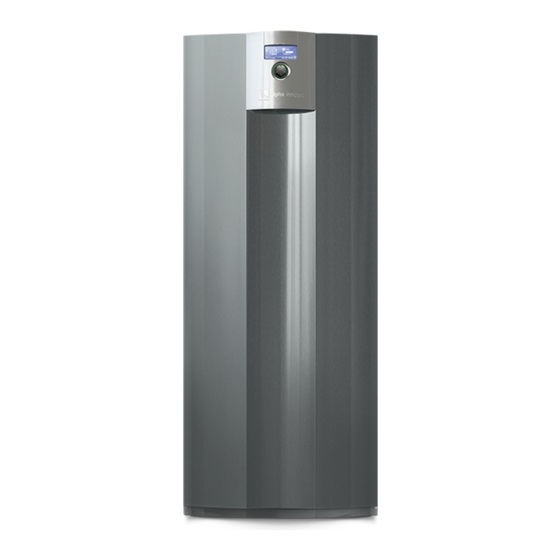
- Page 1 Brine/water heat pumps Operating Manual SW 232H3 - SW 302H3 83057800cUK – Translation into English of the original German operating manual...
- Page 2 Contents 10.2 Maintenance as required ........19 10.3 Yearly maintenance ..........19 10.4 Clean and flush the evaporator und About this operating manual ........ 3 condenser ..............19 Validity ................3 11 Faults Reference documents ..................20 ..........3 1.3 Symbols and identification markings 12 Dismantling and Disposal ..... 3 ........20 Contact ................
-
Page 3: About This Operating Manual
About this operating manual 1.3 Symbols and identification markings This operating manual is part of the unit. Identification of warnings ► B efore working on or with the unit read the operating manual carefully and follow it for all Symbol Meaning activities at all times, especially the warnings and safety instructions. -
Page 4: Intended Use
1.4 Contact – Heating installer – Plumbing installer Addresses for purchasing accessories, for service – Refrigeration system installer (maintenance cases or for answers to questions about the unit and work) this operating manual can be found on the internet at any time and is kept up-to-date: ●... -
Page 5: Avoid Damage To Property
Injuries and environmental damage due to ● Regular servicing and maintenance refrigerant If a system is not planned, designed, started up and operated according to the given requirements, there The unit contains harmful and environmentally is a risk that the following damage and faults will dangerous refrigerant. If refrigerant leaks from the occur: unit:... - Page 6 Description Rating plate Rating plates are attached to the following places on the unit: 3.1 Layout ● on the right-hand outer panel, at the top ● on the rear panel, at the top inside NOTE The rating plate contains the following information at This section essentially...
- Page 7 3.2 Accessories Control unit The following accessories are available for the unit through the manufacturer's local partner: ● Additional masking plate for the front cover panel, if the control is mounted on the wall ● Domestic hot water tank ● Changeover valve, domestic hot water ●...
-
Page 8: Operation And Care
Delivery, storage, transport Cooling and installation Units can be retrofitted with the “Cooling package” accessories. The following options are possible for units with cooling function ( operating manual of the heating and heat pump controller): ATTENTION ● Passive cooling (without compressor) Damage to the housing and the unit components due to heavy objects. -
Page 9: Unpacking And Transport
5.3 Unpacking and transport Dismantle housing panels for transport with handcart or carrying the unit Notes on safe transport Unit is unpacked ( “Unpacking” on page 9). The housing with the unit components and the To avoid damage to the housing panels: module box are heavy ( “Technical data/Scope of –... -
Page 10: Installation
To avoid damage: On a handcart, load the unit Refrigerant Limit value [kg/m³] on its side only. R 134a 0.25 R 404A 0.48 R 407C 0.31 R 410A 0.44 ( “Technical data/Scope of supply” on page 22). Refrigerant capacity [kg] Minimum room volume = Limit value [kg/m³] NOTE... - Page 11 Disconnect the electrical connections: NOTE Disconnect connector (1) at the bottom of the ● If necessary the module box can be – electrical control cabinet. dismantled for easier transport of the unit or for service reasons. – Disconnect connector (2) at the bottom of the electrical control cabinet.
- Page 12 Remove the insulation on the hydraulic connec- Disconnect the hydraulic connections; to do this, tions. push the pipes apart as far as necessary. Remove the 2 side retaining screws. Remove 4 clips on the hydraulic connections. Subject to change without notice | 83057800cUK – Translation into English of the original German operating manual | ait-deutschland GmbH...
- Page 13 Install the module box 11. To protect the floor and move the module box (3) more easily: place boards (4) under it, e.g. from Place the module box carefully in the bottom of the packaging material. the housing and slowly and carefully push it in. 12. Lift and hold nut (1) on the heating flow. – Lift up pipes so that they do not get damaged. Attach the two side retaining screws.
-
Page 14: Install The Hydraulic Connections
6.2 Install the hydraulic connections Basic information on the electrical connection ● The specifications of the local power supply ATTENTION company may apply to electrical connections. Damage to the copper pipes due to unacceptable ● Fit the power supply for the heat pump with an loading! all-pole miniature circuit-breaker with at least 3 mm contact spacing (IEC 60947-2). -
Page 15: Installing The Control
6.4 Installing the control Pull in the cables and conductors and make the connections NOTE Strip the sheathing of all cables to the external loads before laying in the cable duct of the The control can be inserted in a recess in the control box. front panel of the unit or can be installed on the wall. - Page 16 Mount the control on the wall and connect Use cable ties (separate pack) to fix the LIN bus cable to a web of the masking plate around R elease the rear bracket from the control: Press 20 cm in front of the connector (strain relief). together the lugs on the left and right If visually unattractive: Cut off the lugs on the rear of the control (are only needed to insert in the front panel).
-
Page 17: Flushing, Filling And Venting
Flushing, filling and venting 7.2 Heating water quality NOTE Remove the front panel of the ● For detailed information refer, among other things, to the VDI Guidelines module box 2035 “Vermeidung Schäden ► Unscrew the front panel of the module box. Warmwasserheizanlagen” (preventing damage in hot water heating systems). -
Page 18: Flush And Fill The Heating And Domestic Hot Water Charging Circuit
7.4 Flush and fill the heating and C heck the concentration of the water-antifreeze mixture. Frost protection ‚Tecnical Data‘ domestic hot water charging Fill the heat source with the water-antifreeze circuit mixture. Drain pipe of the safety valve is connected. Flush heat source system. The front panel of the module box is unscrewed. ... -
Page 19: Yearly Maintenance
Commissioning Maintenance Relevant planning & design data of the system NOTE is documented in full. We recommend that you sign a maintenance The competent energy supplier has been agreement with accredited heating notified of operation of the heat pump system. company. System is air-free. Installation check using the general checklist 10.1 Basic principles ... - Page 20 Faults Dismantling and Disposal ► Read out the cause of the fault via the 12.1 Dismantling diagnostics program of the heating and heat pump controller. Unit is safely disconnected from the power ► Contact the local partner of the manufacturer or supply and protected against being switched the factory's customer service.
- Page 21 Subject to change without notice | 83057800cUK – Translation into English of the original German operating manual | ait-deutschland GmbH...
- Page 22 Technical data/Scope of supply SW 232H3 – SW 302H3 Performance data: Heating output / COP Leistungsdaten Heizleistung / COP Leistungsdaten Heizleistung / COP SW 232H3 SW 232H3 SW 262H3 at B0/W35 operating point to EN14511 bei B0/W35 Normpunkt nach EN14511 bei B0/W35 Normpunkt nach EN14511 kW ı...
- Page 23 813572 TechDat SW 232H3 Name: Page 1/1 - / PEP014-2015 / Liska / 19.08.2015 813572 Drawing number: Datei: 813572 TechDat SW 232H3 Subject to change without notice | 83057800cUK – Translation into English of the original German operating manual | ait-deutschland GmbH...
-
Page 24: Performance Curves
Zeichnungsnummer: ∆p„ / ∆p„† Heat source free pressure / Heat source with cooling free pressure Datei: 823269 Leistungs-Druckverlustkurven SW 232H3 Subject to change without notice | 83057800cUK – Translation into English of the original German operating manual | ait-deutschland GmbH... - Page 25 SW 262H3 Performance curves Qh (kW) Temp„ (°C) Pe (kW) 35°C 45°C 55°C 65°C Temp„ (°C) Temp„ (°C) ∆p” (bar) ∆p„ (bar) “” (m³/h) “„ (m³/h) 823270 Legende: “” Volumenstrom Heizwasser “„ Volumenstrom Wärmequelle Temp„ Temperatur Wärmequelle Heizleistung Key: DE823000L/170408 Leistungsaufnahme “” Heating water volume flow rate Coeffiicient of performance / Leistungszahl “„...
- Page 26 Performance curves SW 302H3 Qh (kW) Temp„ (°C) Pe (kW) 35°C 45°C 55°C 65°C Temp„ (°C) Temp„ (°C) ∆p„ (bar) ∆p” (bar) “” (m³/h) “„ (m³/h) 823271 Legende: “” Volumenstrom Heizwasser “„ Volumenstrom Wärmequelle Temp„ Temperatur Wärmequelle Heizleistung Key: DE823000L/170408 Leistungsaufnahme “” Heating water volume flow rate Coeffiicient of performance / Leistungszahl “„...
-
Page 27: Dimensioned Drawings
Dimensioned drawings ↑ ↓ ↓ ↑ Item Name Dim. Heat source outlet (from Ø42 Key: D819447 heat pump) Outside diameter All dimensions in mm. Heat source inlet (in heat Ø42 Pos. Bezeichnung Dim. pump) Outside diameter Ø42 Wärmequelle Austritt (aus Wärmepumpe) Heating water inlet (return) Ø35 Aussendurchmesser... - Page 28 Dimensioned drawing of control, wall-mounted bracket Schutzvermerk ISO 16016 beachten Schutzvermerk ISO 16016 beachten Bohrschablone Wall-mounted installation: Blattformat: A4 hoch Maßstab Det. Maßstab Allgemein- Oberflächen toleranz Werkstoff Gewicht Datum Name Benennung Maßbild WZS Erstellt 18.11.2014 Brueckner Gepr. Norm. ait-deutschland GmbH ArtikelNr. Blatt Ø6 Ø6 819447 Industriestraße 3 D - 95359 Kasendorf PEP 015-2014...
-
Page 29: Installation Plans
Installation plans 1000 > 1 Key: DE819456a Version 1 Free space for functionally necessary accessories Free space for service purposes OKF Finished floor level Legende: DE819463 All dimensions in mm Version 1 Freiraum für Servicezwecke Freiraum für funktionsnotwendiges Zubehör Oberkante Fertigfussboden Alle Maße in mm. Subject to change without notice | 83057800cUK –... - Page 30 Installation plans 1000 > 1 Key: DE819456a Version 2 Free space for functionally necessary accessories Free space for service purposes OKF Finished floor level Legende: DE819463 All dimensions in mm. Version 2 Freiraum für Servicezwecke Freiraum für funktionsnotwendiges Zubehör Oberkante Fertigfussboden Alle Maße in mm. Subject to change without notice | 83057800cUK –...
- Page 31 Installation plans > 1 > 1 Key: DE819456a V3 Version 3 Legende: DE819463 FS Free space for service purposes Version 3 OKF Finished floor level Freiraum für Servicezwecke Oberkante Fertigfussboden All dimensions in mm. 1000 Alle Maße in mm. Subject to change without notice | 83057800cUK – Translation into English of the original German operating manual | ait-deutschland GmbH...
- Page 32 Hydraulic integration, unit variant H (heating) Subject to change without notice | 83057800cUK – Translation into English of the original German operating manual | ait-deutschland GmbH...
- Page 33 Hydraulic integration, separate buffer tank Subject to change without notice | 83057800cUK – Translation into English of the original German operating manual | ait-deutschland GmbH...
- Page 34 Subject to change without notice | 83057800cUK – Translation into English of the original German operating manual | ait-deutschland GmbH...
- Page 35 SW 42H3 – SW 192H3 Terminal diagram 1~N/PE/230V/50Hz 3~PE/400V/50Hz OUT4 OUT5 OUT6 OUT7 OUT8 OUT9 OUT10 OUT11 OUT12 OUT13 OUT14 OUT15 OUT16 OUT17 NTC6 NTC7 NTC8 TRL ext. NTC9 NTC10 NTC11 NTC12 NTC13 NTC14 NTC15 Subject to change without notice | 83057800cUK – Translation into English of the original German operating manual | ait-deutschland GmbH...
- Page 36 SW 232H3 – SW 302H3 Circuit diagram 1/3 Subject to change without notice | 83057800cUK – Translation into English of the original German operating manual | ait-deutschland GmbH...
- Page 37 Circuit diagram 2/3 SW 232H3 – SW 302H3 OUT1 OUT6 PWM1 PWM2 Subject to change without notice | 83057800cUK – Translation into English of the original German operating manual | ait-deutschland GmbH...
- Page 38 SW 232H3 – SW 302H3 Circuit diagram 3/3 blue NTC9 brown / blue white green yellow pink NTC13 NTC14 white / blue grey / brown pink / brown violet grey / pink Black red / blue white / green Orange Yellow /2.D6...
- Page 39 10070342 SW 102H1 10074342 SW 122H3 10070442 SW 132H1 10074442 SW 142H3 10070542 SW 172H3 10070642 SW 192H3 10070742 SW 232H3 10074642 SW 262H3 10074742 SW 302H3 10074842 EC Directives Standardized EN 2006/42/EG 2009/125/EG EN 378 EN 349 2006/95/EG 2010/30/EU...
- Page 40 GmbH Industriestraße 3 D-95359 Kasendorf E info@alpha-innotec.de W www.alpha-innotec.de alpha innotec – an ait-deutschland GmbH brand...
Need help?
Do you have a question about the SW 232H3 and is the answer not in the manual?
Questions and answers