
Subscribe to Our Youtube Channel
Related Manuals for Ruckus Wireless ZoneFlex 901-T504-US31


Summary of Contents for Ruckus Wireless ZoneFlex 901-T504-US31
-
Page 1: Installation Guide
ZoneFlex T504 Access Point Installation Guide Applies to 901-T504-US31 and 901-T504-WW31 Part Number 800-71032-001 Rev D Published October 2016 www.ruckuswireless.com... - Page 2 T504 AP Installation Guide, 800-71032-001 Rev D...
-
Page 3: Limitation Of Liability
CONTRACT OR TORT, ARISING FROM YOUR ACCESS TO, OR USE OF, THE MATERIAL. Trademarks Ruckus Wireless, Ruckus, Bark Logo, and ZoneFlex are trademarks of Ruckus Wireless, Inc. in the United States and other countries. All other product or company names may be trademarks of their respective owners. - Page 4 T504 AP Installation Guide, 800-71032-001 Rev D...
- Page 5 Changing the Administrative Password ......................41 Configuring the Security Settings ......................... 41 Configuring Advanced Settings and Features....................41 Reading Related Documentation ........................41 Appendix A: Ruckus Wireless Factory- and Customer-Supplied Parts Appendix B: T504 Mounting Dimensions and Weight Dimensions ..............................45 Weight ................................ 47...
-
Page 6: T504 Ap Installation Guide, 800-71032-001 Rev D
Appendix C: Replacing the F Connector Adapter Appendix D: Rebooting and Resetting the T504 Rebooting and Resetting the AP and CM ..................... 51 Using the Reset Button Inside the AP ......................51 Remotely Rebooting and Factory Resetting the AP ..................52 Rebooting and Factory-Resetting the CM .................... -
Page 7: About This Installation Guide
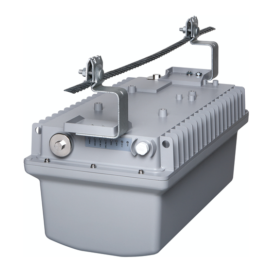
About This Installation Guide This Installation Guide provides information on how to set up the Ruckus Wireless T504 (model 901- T504-US31) strand mount access point (AP) with integrated cable modem (CM) on your network. Topics covered in this guide include basic configuration, operation and mounting. The rest of this document refers to the strand mount access point with integrated cable modem as the T504. -
Page 8: Using This Installation Guide
The T504 installation is completed with four main steps. Each step includes some substeps. Figure shows the main steps, and Table 1 includes the substeps. Figure 2. Adding a T504 to an existing Ruckus Wireless network flowchart Planning the Installation Installing in the Field... - Page 9 About This Installation Guide Using this Installation Guide Table 1. Adding a T504 to an Existing Ruckus Wireless network Section Heading Planning the T504 Installation o T504 Omni Antenna Coverage o Powering Options o Performing a Site Survey Installing the T504...
-
Page 10: Related Documentation
Terms Used in This Guide Terms Used in This Guide Before continuing, Ruckus Wireless recommends that you become familiar with the following terms: o T504: T504 strand mount AP with integrated CM, which includes the AP and CM and the cable strand interface. - Page 11 Planning the T504 Installation Before installing the T504, plan the T504 installation. In this chapter: T504 Omni Antenna Coverage Powering Options Performing a Site Survey T504 AP Installation Guide, 800-71032-001 Rev D...
-
Page 12: T504 Omni Antenna Coverage
Planning the T504 Installation T504 Omni Antenna Coverage T504 Omni Antenna Coverage The T504 includes internal 5GHz and 2.4GHz omnidirectional antennas, and is equipped with a DOCSIS 3.0 cable modem. The T504s are best deployed where internal-antenna lateral beamforming can provide the greatest reach and throughput to a wide coverage area, and provide the greatest distance between APs in a connecting device. -
Page 13: Powering Options
The location and orientation that you choose for the T504 play a critical role in the performance of your wireless network. In general, Ruckus Wireless recommends installing the T504 away from obstructions and sources of interference and ensuring that the AP’s best coverage zone is pointing... - Page 14 Planning the T504 Installation Performing a Site Survey T504 AP Installation Guide, 800-71032-001 Rev D...
- Page 15 Installing the T504 Before installing the T504, Ruckus Wireless recommends that you first complete the procedures described in Planning the T504 Installation. In this chapter: Safety Information Unpacking the T504 AP and CM MAC Addresses, Connectors and Ground Point LEDs and Reset Button/Diagnostic Ethernet Port...
-
Page 16: Safety Information
AP installation must comply with local regulatory requirements, especially with those regulating operation near military and/or weather radar systems. WARNING! Installation of this equipment must comply with local and national electrical codes. Ruckus Wireless strongly recommends that you wear eye protection before mounting WARNING! the AP. CAUTION! Make sure that you form a 80mm - 130mm (3’’-5’’) drip loop in any cable that is attached... -
Page 17: Package Contents
Package Contents A Ruckus Wireless T504 package contains the items listed below: o Ruckus Wireless T504 unit with cable strand hangers, includes one 12mm long stainless steel M6x1 earth ground panhead screw with split lock and flat washers o A one-meter green/yellow earth ground wire with ring terminal... -
Page 18: Ap And Cm Mac Addresses, Connectors And Ground Point
Installing the T504 AP and CM MAC Addresses, Connectors and Ground Point AP and CM MAC Addresses, Connectors and Ground Point The T504 MAC address label lists separate addresses for the internal AP and the cable modem (CM). The MAC address label (1 in Figure 5) is mounted on the end of the T504 with the F type connector and the ground screw (2 and 3 in... -
Page 19: Leds And Reset Button/Diagnostic Ethernet Port
LED is solid. Also blinks during CM boot when power is applied. o On when the Access Point is being managed by a Ruckus Wireless controller. o Off: The Access Point is operating in standalone mode. -
Page 20: Led Startup Sequence
Installing the T504 Dimensions Table 3. LEDs and reset button/diagnostic Ethernet port (Continued) No. Label Description Reset button and diagnostic Ethernet port -- Use a 7/16’’ (11mm) wrench to remove the screw-in access plug. o After removing the plug, press the reset button for ten seconds to reset the AP part of the T504 to factory default. -
Page 21: Deploying The T504
Installing the T504 Deploying the T504 Deploying the T504 In this section, you will mount the T504 in its final mounting location. Perform the following: Mounting the T504 Earth Grounding the T504 Installing the Cable Power Tap Powering the T504 with POC Checking the T504 Signal Level with an RF Power Meter (Optional) Configuring the T504 for the First Time (Optional) Mounting the T504... -
Page 22: Earth Grounding The T504
Installing the T504 Deploying the T504 Earth Grounding the T504 The cable strand is usually earth-grounded, and mounting the T504 on the cable strand earth grounds the T504 chassis as well; if this is the case, skip this procedure and continue with Installing the Cable Power Tap. -
Page 23: Installing The Cable Power Tap
RF signal on the coaxial cable, since the T504 Connector B is used for both electrical power and the RF signal. Ruckus Wireless recommends installing a cable power tap (Antronix MGT2000-SDPE tap, or equivalent) close to the T504. Refer to the manufacturer’s instructions to mount the cable power tap on the coaxial cable. -
Page 24: Powering The T504 With Poc
Installing the T504 Deploying the T504 Powering the T504 with POC 40 to 90 VAC POC is used when the T504 is mounted on a cable strand and powered via an F-type coaxial cable connected to the HFC cable plant. 1 Remove the power jumper from the power tap to remove AC power out of the power tap. -
Page 25: Checking The T504 Signal Level With An Rf Power Meter (Optional)
Installing the T504 Deploying the T504 Checking the T504 Signal Level with an RF Power Meter (Optional) The CMAP cable modem is just like the standard DOCSIS 3.0 modem installed at home. Connect an RF power meter to the cable from the cable power tap. Select a CATV power passing tap that supplies a signal level between -12dBmV and +16dBmV at its output (prefer 0dBmV to 6dBmV). -
Page 26: Configuring The T504 For The First Time (Optional)
Installing the T504 Deploying the T504 Configuring the T504 for the First Time (Optional) NOTE The T504 normally receives its latest AP and CM firmware downloads and initial configurations from the cable modem termination system high speed data services (CMTS) equipment when it powers up;... - Page 27 Installing the T504 Deploying the T504 6 Select IP address automatically, and then configure the IP address settings with the values listed in Table 6. For a sample configuration, refer to Figure Table 6. Configure your computer’s IP address settings IP address Use the following IP address.
- Page 28 Installing the T504 Deploying the T504 o The IP address assigned to the CM by the CMTS DHCP server. o An administrative computer as configured as described in Preparing the Administrative Computer. o One Cat5e or better Ethernet cable. o 7/16’’ (11mm) wrench. 2 Use a 7/16’’...
- Page 29 Installing the T504 Deploying the T504 There are two tables on the Software Status page -- - Information and Status. Table 7 Table 8 describe the information that these tables display. Table 7. Information (software) table Item Description Standard Specification The standard with which the device is compliant.
- Page 30 Installing the T504 Deploying the T504 Figure 11. Connection Status page - Page 2 of 2 Continue with Configuring the Downstream Frequency. Configuring the Downstream Frequency The Configure Status page allows you to set the downstream frequency for the cable modem. Configuring the downstream frequency enables the device to quickly obtain a direct frequency lock with the CMTS upon bootup and helps to save several minutes of scanning for an available downstream frequency from the CMTS.
-
Page 31: Re-Installing An Access Plug Or Hardline Adapter
Deploying the T504 Figure 13. Security Status page 3 Ruckus Wireless recommends that you change the login and/or password as follows: a Enter a new CM user ID in Password Change User ID. b Enter a new CM user password in New Password. -
Page 32: Verifying Cm And Ap Operation
Installing the T504 Verifying CM and AP Operation Re-Installing an Access Plug or Hardline Adapter If you have replaced the F connector/stinger/hardline adapter or removed a screw-in access plug (to connect the administrative computer, or use the AP and CM reset button), then re-install the access plug or stinger as follows. -
Page 33: Retrieving The Cm's Mac Address
Operating and Troubleshooting the T504 This section lists some information that may be useful in operating and troubleshooting the T504. Topics discussed include: Retrieving the CM’s MAC Address Rebooting and Resetting the T504 How Radio Frequency Scanning Works Retrieving the CM’s MAC Address There are some configuration operations that require you to enter the CM’s MAC address. - Page 34 Operating and Troubleshooting the T504 Rebooting and Resetting the T504 2 Connect an administrative computer to the same subnet as the T504. 3 On the administrative computer, start the Telnet or SSH (secure shell) client program. 4 Log onto to the AP using Telnet or SSH with the following logon details: o User names: super o Password: sp-admin 5 When command prompt appears, enter the following command:...
-
Page 35: How Radio Frequency Scanning Works
Operating and Troubleshooting the T504 How Radio Frequency Scanning Works How Radio Frequency Scanning Works The following steps describe how a DOCSIS-compliant T504 performs radio frequency scanning: 1 Looks at the last ‘‘known good channel’’ (repeat this every 64 channel checks). 2 Checks the sixteen last known frequencies (repeat this every 32 channel checks). - Page 36 Operating and Troubleshooting the T504 How Radio Frequency Scanning Works T504 AP Installation Guide, 800-71032-001 Rev D...
-
Page 37: Changing The Administrative Password
What to Do Next The following are some of the post-installation tasks that Ruckus Wireless recommends. Refer to the Ruckus Wireless Outdoor Access Point User Guide for more information on configuring and managing the AP. Changing the Administrative Password Management access to the Web interface of the AP is controlled through administrative user name and password. - Page 38 What to Do Next Reading Related Documentation T504 AP Installation Guide, 800-71032-001 Rev D...
- Page 39 Appendix A: Ruckus Wireless Factory- and Customer-Supplied Parts Table 9. Factory-supplied and customer-supplied parts Part Ruckus T504 Kit or Notes Wireless P/N Customer Supplied 1m lugged earth T504 kit ground wire Cable power tap Customer Antronix and connecting supplied MGT2000-SDPE...
- Page 40 T504 AP Installation Guide, 800-71032-001 Rev D...
-
Page 41: Dimensions
Appendix B: T504 Mounting Dimensions and Weight Dimensions Figure 14. T504 length--all dimensions in millimeters and [inches] T504 AP Installation Guide, 800-71032-001 Rev D... - Page 42 Dimensions Figure 15. T504 height and width--all dimensions in millimeters and [inches] T504 AP Installation Guide, 800-71032-001 Rev D...
-
Page 43: Weight
Weight Weight The T504 weighs 9.5 pounds. For other specifications, refer to the Ruckus Wireless data sheet. T504 AP Installation Guide, 800-71032-001 Rev D... - Page 44 Weight T504 AP Installation Guide, 800-71032-001 Rev D...
- Page 45 Appendix C: Replacing the F Connector Adapter If you need to replace the 3/4’’ KS male to F female port adapter (stinger or hardline adapter), then complete the following: 1 Collect the following tools and supplies: o Customer-supplied 3/4’’ KS male to F female port adapter (stinger) o 7/16’’...
- Page 46 Figure 17. F connector stinger pin length 17.0mm +/-1.0mm (0.63’’ +/- 0.04’’) NOTE The Phillips retaining screw (1 in Figure 18) holding down the stinger pin (2 in Figure 18) uses a flat washer (3 in Figure 18) to make good electrical contact with the stinger pin. The flat washer must go between the Phillips retaining screw head and the stinger pin.
- Page 47 Appendix D: Rebooting and Resetting the T504 Rebooting and Resetting the AP and CM Rebooting and Factory-Resetting the CM Rebooting and Resetting the AP and CM CAUTION! Performing this procedure resets the AP and CM parts of the T504 to their factory default settings.
- Page 48 You have completed resetting the AP and CM to their factory default settings and/or rebooting the AP and CM. Remotely Rebooting and Factory Resetting the AP NOTE Before starting this procedure, you must first obtain the related MIBs from Ruckus Wireless. Contact your authorized Ruckus Wireless sales representative or Ruckus Wireless Support. Visit http://support.ruckuswireless.com/contacts for Ruckus Wireless Support contact information.
- Page 49 Factory resetting returns the CM part of the T504 to its factory default settings. NOTE Before starting this procedure, you must first obtain the related MIBs from Ruckus Wireless. Contact your authorized Ruckus Wireless sales representative or Ruckus Wireless Support. Visit http://support.ruckuswireless.com/contacts for Ruckus Wireless Support contact...
- Page 50 T504 AP Installation Guide, 800-71032-001 Rev D...
- Page 51 T504 AP Installation Guide, 800-71032-001 Rev D...
- Page 52 Copyright © 2006-2016. Ruckus Wireless, Inc. 350 West Java Dr. Sunnyvale, CA 94089. USA www.ruckuswireless.com...
Need help?
Do you have a question about the ZoneFlex 901-T504-US31 and is the answer not in the manual?
Questions and answers