Advertisement
Quick Links
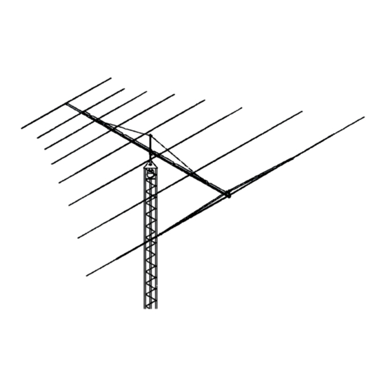
SPECIFICATIONS:
Model ......................................... 8-30LP9
Frequency Range ....................... 8 To 30 MHz
*Gain .......................................... 9.5 dBi @ 70' OG
Front to back .............................. 12 dB
Feed Impedance. ....................... 50 Ohms Unbalanced
Maximum VSWR ........................ 1.9:1
Input Connector .......................... SO-239, "N" Female avl.
FEATURES:
This special hybrid log periodic is a rugged versatile performer designed for years of trouble free service. Ma-
chined aluminum element to boom clamps and solid fiberglass rod center insulators are just a few of the
unique structural features in this remarkable antenna. The 8-30LP9 is a single antenna system that matches
up with today's modern solid state equipment.
Maritime, Government, Commercial, MARS and Scientific users will find that the 8-30LP9 reliably fills a variety
of communication requirements. When properly installed at 65 feet or higher this nine element antenna is a
world wide, world-class performer. Solid electrical and structural design will maintain communications when
other antennas have long since faded into the noise.
M2 Antenna Systems, Inc. 4402 N. Selland Ave. Fresno, CA 93722
M2 Antenna Systems, Inc.
Model No: 8-30LP9
*Subtract 2.14 from dBi for dBd* (OG = Over Ground)
Tel: (559) 432-8873 Fax: (559) 432-3059 Web: www.m2inc.com
©2015 M2 Antenna Systems Incorporated
Power Handling .......................... 3 Kw, Higher avl.
Boom Length / Dia ...................... 48' X 3" X 0.125 wall
Maximum Element Length .......... 50'
Turning Radius: .......................... 36'
Wind area / Survival ................... 18 Sq. Ft. / 125 MPH
Weight / Ship Wt. ........................ 170 lbs. / 190 lbs.
09/21/15
Rev.00
Advertisement

Related Manuals for M2 Antenna Systems 8-30LP9


Summary of Contents for M2 Antenna Systems 8-30LP9
- Page 1 The 8-30LP9 is a single antenna system that matches up with today’s modern solid state equipment.
- Page 2 8-30LP9 ASSEMBLY MANUAL BEFORE YOU BEGIN: Look over the DETAIL DRAWINGS, ELEMENT ASSEMBLY AND DIMENSION SHEET, to get familiar with the various parts of the log periodic. Tools handy for assembly process: Phillips screwdriver, 11/32, 7/16, 1/2, & 9/16” nut drivers, end wrenches and/or sockets, measuring tape.
- Page 3 8-30LP9 ASSEMBLY MANUAL ELEMENT MOUNTS, #5 THROUGH 8 3. ELEMENT #5 MOUNTING PLATES. Element #5 uses two 2-1/2 x 4” plates and TWO SADDLES to attach it to the boom. A 7/8” diameter fiberglass rod gets two 7/8” I.D. poly rings pushed on and centered just over 4”...
- Page 4 8-30LP9 ASSEMBLY MANUAL NOTE: THE FOLLOWING ELEMENTS HAVE SLEEVED SECTIONS. MOST ARE IN PLACE FROM THE FACTORY BUT IF NOT, WIPE THE SLEEVE CAREFULLY AND LUBE LIGHTLY WITH OIL OR W4-40 PRIOR TO INSERTION. IF THE SLEEVE STICKS OR BINDS AT ALL, STOP, STOP STOP.
- Page 5 8-30LP9 DIMENSION SHEET...
- Page 6 8-30LP9 ELEMENT ASSEMBLY...
- Page 7 8-30LP9 ASSEMBLY MANUAL 4. Element #3 is has 3 internal sleeves as noted on the ELEMENT ASSEMBLY drawing. Again start at the butt and insert the 1-3/8 x 25” sleeve and hold in place with a 1/4-20 x 2” bolt and locknut but don’t tighten.
- Page 8 LINEAR LOADED ELEMENT ASSEMBLY...
- Page 9 8-30LP9 ASSEMBLY MANUAL 7. BOOM ASSEMBLY Wipe off any dirt or grit from the coupling rings on the end of the long 3” section. Also clean the inside of the 4” x 20 foot section. Lubricate the inside of the 4” tube and the coupling rings lightly with oil or zinc paste Gently insert the 3”...
- Page 10 8-30LP9 ASSEMBLY MANUAL 12. OVERHEAD BOOM SUPPORT SYSTEM. Install a temporary mast if possible to get the overhead system just right before installing the antenna. Attach one end of the HPTG-4000 Philistran cable at the eyebolt at the REAR end of the boom.
- Page 11 8-30LP9 PARTS & HARDWARE DESCRIPTION .................... QTY Boom section, 4” x .125 x 240" ..............1 Boom section, 3 x .125 x 240" straight w/ coupling rings to 3-3/4” ID ..1 Boom section, 3 x .125 x 108" swaged ............1 Sleeve, outer, 1-5/8”...
- Page 12 8-30LP9 PARTS & HARDWARE IN HARDWARE BOX Saddle, 4” machined alum................16 Saddle, 1-1/4”, machined alum..............12 Clamp plate, 1/2 x 3 x 6", .500 radius, alum ..........2 Clamp plate, 3/8 x 2-1/2 x 4" alum.............. 5 Clamp cap plate, 1/4 x 1-1/2 x 4"...
- Page 13 8-30LP9 PARTS & HARDWARE IN HARDWARE BAG Bolt, 3/8-16 x 5-1/2”, stainless ..............16 Bolt, 3/8-16 x 4-1/2” stainless ..............2 Nut, 3/8-16, locking, stainless ..............26 Bolt, 5/16-18 x 2-1/2” stainless ..............12 Nut, 5/6-18, locking, stainless ..............12 Nut, 5/16-18 stainless ..................
Need help?
Do you have a question about the 8-30LP9 and is the answer not in the manual?
Questions and answers