Advertisement
SPECIFICATIONS:
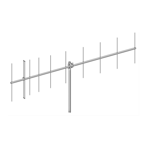
Model ......................................... 222-10EZ
Frequency Range ....................... 222 To 226 MHz
*Gain .......................................... 14.1 dBi
Front to back .............................. 23 dB Typical
Beamwidth ............................... E=34° H=39°
Feed type ................................... "T" Match
Feed Impedance. ....................... 50 Ohms Unbalanced
Maximum VSWR ........................ 1.2:1
Input Connector .......................... "N" Female
FEATURES:
The 222-10EZ is an easily assembled, medium sized, computer designed Yagi that covers 222 to 226 MHz with
flat gain and VSWR. Strong, yet lightweight and streamlined, it compliments any VHF system. The heart of the 222-10EZ
is a unique Driven Element Module with superior weather resistance and power handling abilities. All connectors are O-
ring sealed to the CNC machined block and internal connections are sealed in a space-age silicone gel with a dielectric
strength nearly 4 times greater than air. The Balun coax connectors are triple sealed.
Other key mechanical and electrical parts are CNC machined from 6061-T6 aluminum and all hardware except U-
bolts is stainless steel. It features our silicone-gel sealed, weatherproof driven element assembly and a unique internal
balun. Want higher power capability or some other change? Please contact the factory for details.
M2 Antenna Systems, Inc. 4402 N. Selland Ave. Fresno, CA 93722
M2 Antenna Systems, Inc.
Model No: 222-10EZ
*Subtract 2.14 from dBi for dBd
Tel: (559) 432-8873 Fax: (559) 432-3059 Web: www.m2inc.com
©2015 M2 Antenna Systems Incorporated
Power Handling .......................... 1.5 kW
Boom Length / Dia ...................... 9' 9" / 1"
Maximum Element Length .......... 26-3/8"
Turning Radius: .......................... 5' 6"
Stacking Distance ....................... 78" High & 80" Wide
Mast Size .................................... 1-1/2" to 2" Nom.
Wind area / Survival ................... 0.075 Sq. Ft. / 100MPH
Weight / Ship Wt. ........................ 4 Lbs. / 5 Lbs.
06/29/15
Rev.01
Advertisement
Table of Contents

Related Manuals for M2 Antenna Systems 222-10EZ


Summary of Contents for M2 Antenna Systems 222-10EZ
-
Page 1: Specifications
The 222-10EZ is an easily assembled, medium sized, computer designed Yagi that covers 222 to 226 MHz with flat gain and VSWR. Strong, yet lightweight and streamlined, it compliments any VHF system. The heart of the 222-10EZ is a unique Driven Element Module with superior weather resistance and power handling abilities. All connectors are O- ring sealed to the CNC machined block and internal connections are sealed in a space-age silicone gel with a dielectric strength nearly 4 times greater than air. - Page 2 222-10EZ ASSEMBLY MANUAL Tools required: screwdriver, 11/32”, 7/16”, and 1/2” end wrenches and / or sockets, measuring tape. 1. Assemble the two 1” boom sections using 8-32 x 1-1/4" screws and locknuts. 2. Lay out the 3/16” elements by length and position as shown the DIMENSION sheet. Start with the REFLECTOR element.
- Page 3 222-10EZ ASSEMBLY MANUAL 6. Mount the DRIVEN ELEMENT BLOCK ASSEMBLY to the top of the boom using a single 8-32 X 1- 1/4" screw. Orient the block with feed connector facing to the FRONT. 7. Attach balun, routing coax along boom in a single loop. Tighten the connectors gently using a 7/16"...
- Page 4 222-10EZ DIMENSION SHEET...
- Page 5 222-10EZ PARTS & HARDWARE DESCRIPTION BOOM SECTION, 1 X .058 X 60” SOE ..... 1 BOOM SECTION, 1 X .058 X 60” STR ....1 ELEMENTS, 3/16 ROD x Dimension Sheet ..10 DRIVEN ELEMENT BLOCK ASSEMBLY ..1 BALUN, RG-6 1/2 WAVE ........1 BOOM-TO-MAST PLATE, .188 X 3 X 4”...
Need help?
Do you have a question about the 222-10EZ and is the answer not in the manual?
Questions and answers