Advertisement
Quick Links
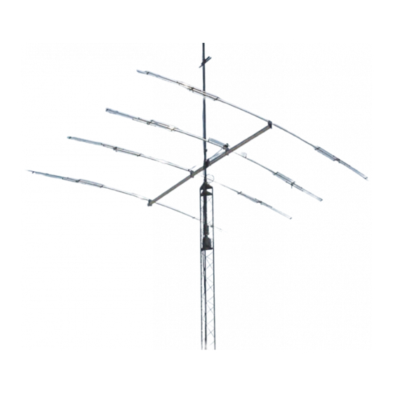
SPECIFICATIONS:
Model ......................................... KT34M2
Frequency Range ....................... 14.0-14.350 MHz
Frequency Range ....................... 21.0-21.450 MHz
Frequency Range ....................... 28.0-29.0 MHz
*Gain in free space ..................... See Chart
Front to back .............................. See Chart
Feed type ................................... "T" Match
Feed Impedance. ....................... 50 Ohms Unbalanced
Maximum VSWR ........................ 1.5:1
FEATURES:
The KT34M2 is now the best performing and strongest short tribander available today. All four elements resonant
on each band. A dual driven element allows a beautiful flat match, broad gain, and high front to back curves across 10,
15, and 20M. A 3kW 4:1 balun efficiently matches the antenna to 50. All sheet metal parts has been upgraded to our
new machined shorting bars, stiffening and strengthening the antenna noticeably. The long term performance is en-
hanced by the total contact machined joints. This antenna will be competitive with most monobanders! Be surprised, get
the NEW KT34M2.
M2 Antenna Systems, Inc. 4402 N. Selland Ave. Fresno, CA 93722
M2 Antenna Systems, Inc.
Model No: KT34M2
*Subtract 2.14 from dBi for dBd
Tel: (559) 432-8873 Fax: (559) 432-3059 Web: www.m2inc.com
©2015 M2 Antenna Systems Incoporated
Input Connector .......................... SO-239, Others avl.
Power Handling .......................... 3 kW, Higher avl.
Boom Length / Dia ...................... 16' / 3.0 x .065 Wall
Element Length / Dia. ................. 25' / 1" To 1/2"
Turning Radius: .......................... 15'
Stacking Distance ....................... 37' To 43'
Mast Size .................................... 2" to 3 " Nom.
Wind area / Survival ................... 4.5 Sq. Ft. / 100 MPH
Weight / Ship Wt. ........................ 40 Lbs. / 62 Lbs.
10m
f, MHz G, dBi F/B, dB
28.0
7.3
18
28.2
7.3
23
28.4
7.4
25
28.6
7.5
24
29.2
7.6
20
15m
f, MHz G, dBi F/B, dB
21.0
6.9
19
21.1
6.9
22
21.2
7.0
24
21.3
7.0
24
21.45
7.1
23
20m
f, MHz G, dBi F/B, dB
14.0
6.5
17
14.1
6.6
24
14.2
6.7
21
14.35
6.8
23
11/14/18
Rev.03
Advertisement

Related Manuals for M2 Antenna Systems KT34M2


Summary of Contents for M2 Antenna Systems KT34M2
-
Page 1: Specifications
FEATURES: The KT34M2 is now the best performing and strongest short tribander available today. All four elements resonant on each band. A dual driven element allows a beautiful flat match, broad gain, and high front to back curves across 10, 15, and 20M. - Page 2 KT34M2 ASSEMBLY MANUAL Tools: Phillips head screw driver, ‘green’, 11/32” nut driver, 7/16” wrench, 7/16” socket, socket wrench, tape measure, and a friend. NOTE: To prevent galling of the stainless steel hardware, apply a light coating of Penetrox to all bolts and screws.
- Page 3 KT34M2 ASSEMBLY MANUAL 3. CAPACITOR ASSEMBLIES ONTO LONGER 3/8” TUBES Locate the (8) longer 3/8” diameter tubes. Upon inspecting the tubes, you’ll notice there are two holes drilled on one side only. These holes equalize the atmospheric pressure in the capacitors and prevent moisture build up inside the capacitor tubes.
- Page 4 KT34M2 ASSEMBLY MANUAL 4. GENERAL ASSEMBLY OF HALF ELEMENT SECTIONS We recommend assembling the half element sections on a clean, flat surface. There is an “DIMENSION/ ASSEMBLY” drawing for each of the four elements with both the right and left halves shown on each page. We also recommend briefing yourself with the general directions before skipping to the assembly drawings.
- Page 5 KT34M2 ASSEMBLY MANUAL...
- Page 6 KT34M2 ASSEMBLY MANUAL...
- Page 7 KT34M2 ASSEMBLY MANUAL...
- Page 8 KT34M2 ASSEMBLY MANUAL...
- Page 9 KT34M2 DIMENSION SHEET 48.50” 26.75” 47.25” 43.75” 25.00” 44.00”...
- Page 10 KT34M2 ASSEMBLY MANUAL 5. HF CLAMP PLATE PAIR ASSEMBLY Locate the 8 element clamp plates, the Balun ‘L’-Bracket, 2-1/2” U-bolt & Saddle, and element clamp cap. Assemble the plates into four pairs with the radii facing each other using four 1/4-20 x 2” bolts. On one of the ‘alike’-pair combinations, attach the Balun ‘L’-Bracket to the outside clamp plate with the flat side up and higher...
- Page 11 KT34M2 ASSEMBLY MANUAL location for the outside edge of the element clamp on the REAR DRIVEN ELEMENT assembly with a marking pen or pencil. Install the REAR DRIVEN ELEMENT as you did for the REFLECTOR Make sure you follow the element placement on the DIMENSION SHEET.
- Page 12 SAME BAND AS THE TRIBANDER. Serious interaction will result and loss of performance of both antennas maybe noted. Two KT34M2 tribanders can be stacked together but the spacing must be at least 32 feet apart. When stacking this antenna with other H.F. models like 17 and 12 meters, maintain at least 8’ separation; more if practical.
- Page 13 KT34M2 PARTS & HARDWARE DESCRIPTION Boom section, 3”x .065 x 95” SOE, holes in swage ... 1 Boom section, 3” x .065 x 95” SOE, holes both end ..1 Boom section, 3” x .065 x 12” ..........1 Element, 1” x 72 SOE ............8 Sleeve, center, 7/8 x .058 x 36”...
- Page 14 KT34M2 PARTS & HARDWARE IN BAG #6 (MISCELLANEOUS) Clamp Block, 3/8” ..............8 Phasing Line Insulator black delrin, 3/4 x 3” ......1 Balun ‘L’-Bracket, 1” x 1” x 4” ..........1 Balun Straps ................ 2 Fiberglass Insulator, 3/8” x 10” ..........1 Poly Disk Insulator, 7/8”...
Need help?
Do you have a question about the KT34M2 and is the answer not in the manual?
Questions and answers