Table of Contents
Advertisement
Quick Links
A994 OWNER'S MANUAL CONTENTS
1. INTRODUCTION ................................................................................ 2
2. SAFETY PRECAUTIONS ..................................................................
3. LIST OF PARTS .................................................................................
4. ASSEMBLE THE PRODUCT .............................................................
STEP 1 Install Frames and Connector ................................................... 6
STEP 2 Install the Right/Left Handle Frame ..........................................
STEP 3 Install the Seat Back and Arm Cushion ....................................
STEP 4 Secure the Unit ......................................................................... 10
STEP 5 Level the Product ...................................................................... 11
STEP 6 Unit Inspection .......................................................................... 12
5. OPERATE THE PRODUCT ............................................................... 13
OPERATION Operate the Product ........................................................ 13
OPERATION Exercising Instructions ..................................................... 14
6. MAINTENANCE ................................................................................ 16
MAINTENANCE Safety Precautions ................................................... 16
MAINTENANCE Schedule .................................................................... 17
MAINTENANCE Task List .................................................................... 18
MAINTENANCE One-Year Maintenance Log ....................................... 19
7. CONSIGNES DE SÉCURITÉ IMPORTANTES ................................. 20
8. APPENDIXES ................................................................................... 21
APPENDIXES Exploded Diagram ........................................................ 21
*We reserve the right to revise this manual at any time without notice.
3
4
6
8
9
Advertisement
Table of Contents

Subscribe to Our Youtube Channel
Related Manuals for SportsArt Fitness A994


Summary of Contents for SportsArt Fitness A994
-
Page 1: Table Of Contents
A994 OWNER’S MANUAL CONTENTS 1. INTRODUCTION ................2 2. SAFETY PRECAUTIONS ..............3. LIST OF PARTS ................. 4. ASSEMBLE THE PRODUCT ............. STEP 1 Install Frames and Connector ........... 6 STEP 2 Install the Right/Left Handle Frame .......... STEP 3 Install the Seat Back and Arm Cushion ........ -
Page 2: Introduction
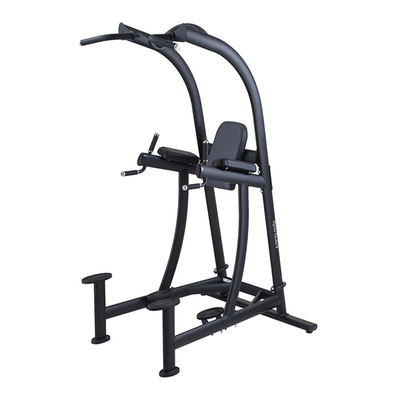
1. INTRODUCTION Congratulations on the purchase of a high quality SportsArt product, the A994 Leg Raise/Chin Dip. Constructed of high quality materials and designed for years of reliable performance, this product was made for full commercial use. Before this product is assembled or operated, we recommend that you familiarize yourself with this manual. -
Page 3: Safety Precautions
2. SAfETy PRECAUTIONS This product was designed and built for optimum safety. However certain precau- tions apply during the use of this product. Please note the following safety precau- tions: • Please read the entire manual before assembly and operation. Make sure the product is installed and operated as instructed in this manual. -
Page 4: List Of Parts
3. LIST Of PARTS Assembly Parts Name Qty. No. Name Qty. A1 Left pull up bar frame A8 Seat back A2 Connector A9 Arm cushion A3 Right pull up bar frame A10 Rear support A4 Right handle frame A11 Floor fixing bracket A5 Left handle frame A12 Owner’s manual A6 Front support... - Page 5 Components in the Hardware Kit Name Qty. Specification Notes Hex nylon nut Washer D16*d10.2*t1.0 Inner hex screw M10*P1.5*L130 Spring washer Connecter Board Hex head screw M10*P1.5*L30 Spring washer Flat washer D21*d10.5*t2 Double Open End wrench 13mm*17mm L-shaped Allen wrench M5*L114mm*W24 Screwdriver shank Flat and Phillips Hardware Kit...
-
Page 6: Assemble The Product
4. ASSEMBLE THE PRODUCT Follow instructions below to assemble this product. Note that in this manual the words “left” and “right” are used to refer to the product and its parts. As such, these designations correspond to the “left” and “right” sides of a person in position to exercise on this product. - Page 7 STEP 1 Install frames and Connector (Continued) (a) Align the connecter (A2) to the holes in the left/right pull up bar frame (A1) (A3) and then loosely secure the assembly in place with screws (22) as shown. Do not tighten nuts yet. (b) Remove screws (31) from the front support (A6).
-
Page 8: Step 2 Install The Right/Left Handle Frame
STEP 2 Install the Right/Left Handle frame (a) First, remove screws (33) from the right/left handle frame (A4) (A5). Attach the right/left handle frame (A4) (A5) to the left/right pull up bar frame (A1) (A3) and front support (A6) and then secure the assembly in place with screws (21) (33) as shown. -
Page 9: Step 3 Install The Seat Back And Arm Cushion
STEP 3 Install the Seat Back and Arm Cushion First, remove screws (34) from the seat back (A8) and arm cushion (A9). Attach the seat back (A8) and arm cushion (A9) to the seat back frame (A7) and right/left handle frame (A4) (A5) and then secure the assembly in place with screws (34) as shown. -
Page 10: Step 4 Secure The Unit
STEP 4 Secure the Unit Secure the floor fixing bracket (A11) to the floor with the floor fixing bolt, nut and washer as shown to make sure the machine is firmly fixed to the floor when operating. (Level the machine before securing the floor fixing bolt.) (Note: The screw hole of floor fixing bracket is Ø9mm, please make sure using the suitable floor fixing bolt and drilling the proper hole on the floor.) -
Page 11: Step 5 Level The Product
STEP 5 Level the Product Please follow instructions (a) through (c) below to level the unit. (a) Loosen the leveler nuts. (b) Rotate the leveler feet downward, touching the floor. (c) Rotate the leveler nuts upward, against the frame of the product, to secure this position. -
Page 12: Step 6 Unit Inspection
STEP 6 Unit Inspection After completing the assembly or regular maintenance, please follow instruc- tions (a) through (c) below to inspect the unit. If the unit is disassembled or has been damaged in any way, it might cause injuries or cause the unit to fail. -
Page 13: Operate The Product
5. OPERATION THE PRODUCT OPERATION Safety Operating Area (a) Safety clearance required as shown below. Do not allow people to be near this area when operating. (b) Noise emission under load is higher than without load. (c) Over exercising or improper workout position may result in serious injury. (d) This product is intended for exercise abdomen, arms and back. -
Page 14: Operation Exercising Instructions
OPERATION Exercising Instructions * Please exercise within the range of your skill and training. DO NOT work to exhaustion. * Please follow the operating instructions as below to test operation. * All users operate this machine must be supervised under coaches instructions at all times in order for safety. - Page 15 OPERATION Exercising Instructions (Continued) fig 2. Exercise arms and chest (*Please follow coaches’ instructions.) fig 3. Exercise back (*Please follow coaches’ instructions.)
-
Page 16: Maintenance
6. MAINTENANCE This section covers maintenance topics and includes a maintenance schedule, task list, and log. MAINTENANCE Safety Precautions ● Please follow standard safety precautions when servicing this product. ● Do NOT use a water damp towel to clean the product and do perform the following maintenances. -
Page 17: Maintenance Schedule
MAINTENANCE Schedule Area Week Month Quarter Year Notes Exterior Clean. Inspect for looseness Screws and secure if necessary. -
Page 18: Maintenance Task List
MAINTENANCE Task List Like cars, fitness products require maintenance. Regular maintenance ex- tends product life, and failure to maintain products can void the manufac- turer’s warranty. Copy the maintenance log sheet, and record maintenance work for each fitness product. Daily tasks 1. -
Page 19: Maintenance One-Year Maintenance Log
MAINTENANCE One-year Maintenance Log Facility:_______________________ Supervisor:____________________ Product model number:__________ Serial number:_________________ Start date: ____________________ End date:_____________________ Daily Tasks Weeks 1-7 Weeks 8-14 Weeks 15-21 Week 22-28 Completed Daily Tasks Week 29-35 Week 36-42 Week 43-49 Week 50-52 Completed Weekly Tasks Weeks 1-7 Weeks 8-14 Weeks 15-21 Weeks 22-28... -
Page 20: Consignes De Sécurité Importantes
7. CONSIGNES DE SÉCURITÉ IMPORTANTES Le produit SportsArt a été conçu et fabriqué afin d’assurer une sécurité optimale. Cepen- dant certaines précautions s’appliquent chaque fois que vous utilisez votre produit. • Lisez entièrement le manuel avant l’assemblage et l’utilisation. Veuillez aussi noter les consignes de sécurité... -
Page 21: Appendixes
8. APPENDIXES APPENDIXES Exploded Diagram Note: We reserve the right to revise the following diagrams at any time without notice or obligation to notify any person of such revisions or changes. Please visit our official website www.gosportsart.com for the latest version. - Page 22 your Authorized Distributor...
Need help?
Do you have a question about the A994 and is the answer not in the manual?
Questions and answers