
Related Manuals for Onicon F-5100


Summary of Contents for Onicon F-5100
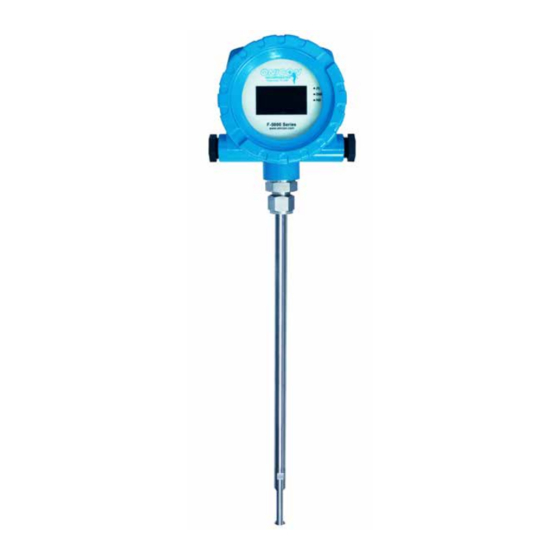
- Page 1 F-5100 Insertion Thermal Mass Flow Meter Installation and Operation Guide | sales@mvandc.com | Phone: 877.566.3837 | Fax: 925.407.2903 www.mvandc.com...
-
Page 2: Safety Information
ONICON assumes no responsibilities for this product except as stated in the warranty. • If the customer or any third party is harmed by the use of this product, ONICON assumes no responsibility for any such harm owing to any defects in the product which were not predictable, or for any indirect damages. - Page 3 TABLE OF CONTENTS INTRODUCTION ....................5 PURPOSE OF THIS GUIDE ...............5 TYPICAL INSERTION THERMAL MASS FLOW METER .......5 STANDARD FEATURES AND SPECIFICATIONS ........6 ADDITIONAL REQUIRED HARDWARE ...........7 ADDITIONAL HARDWARE THAT MAY BE REQUIRED ......8 1.5.1 Flow Conditioners ...............8 1.5.2 Additional Remote Mount Cable ..........8 WORKING ENVIRONMENT ..............9 WARRANTY &...
- Page 4 START-UP & COMMISSIONING FOR ONICON INSERTION THERMAL MASS FLOW METERS ....................23 DISPLAY ....................23 POWERING THE METER ................23 HELPFUL HINTS FOR START-UP & COMMISSIONING ......23 START-UP & COMMISSIONING .............24 START-UP & COMMISSIONING WORKSHEET ........25 TROUBLESHOOTING GUIDE ................26 APPENDIX REMOTE MOUNT MECHANICAL HARDWARE...
-
Page 5: Introduction
We, at ONICON Incorporated, would like to thank you for purchasing our quality American made F-5100 Series Thermal Mass Flow Meter. As our valued customer, our commitment to you is to provide fast reliable service, while continuing to offer you quality products to meet your growing flow measurement needs. -
Page 6: Standard Features And Specifications
STANDARD FEATURES AND SPECIFICATIONS CALIBRATION Every ONICON thermal mass flow meter is wet calibrated in a flow laboratory against standards that are directly traceable to N.I.S.T. A certificate of calibration accompanies every meter. Each meter is calibrated for use with a specific gas. -
Page 7: Additional Required Hardware
ADDITIONAL REQUIRED HARDWARE All ONICON insertion thermal mass meters can be installed and removed via a ¾” or larger full port ball valve without disrupting flow. The terms “Standard” and “Hot Tap” refer to the installation method only. Standard Installation: Occurs during new construction or Compression Fitting scheduled shutdown. -
Page 8: Additional Hardware That May Be Required
8” Flow Conditioner, Sch40 1.5.2 Additional Remote Mount Cable ONICON remote mount meters are provided with 25 ft of cable. Additional cable lengths of up to 1000 ft may be added without affecting the calibration of the meter. Part #... -
Page 9: Working Environment
Appendix A-6, ONICON’s Conditions of Sale for details. Serial Number The serial number of your F-5100 series flow meter is located on the nameplate attached to the top of the enclosure. This serial number will also be located on the remote sensor for remote mount meters. -
Page 10: Unpacking
All ONICON products are shipped insured unless the customer specifically requests otherwise. Please notify the shipping company and ONICON immediately if any items are damaged in transit. Save all packing material for inspection by the shipper. CHECKING THAT YOU RECEIVED EVERYTHING... -
Page 11: Installation, Removal And Adjustment
Contact ONICON for assistance if this relationship does not allow for viewing the display. - Page 12 180° 2 X Diameter CLEARANCE Clearwater, FL USA REQUIRED ᴫ COMM F-5000 Series FOR INSTALLATION www.onicon.com 30” - 36” Depending on pipe size FLOW 2 Dia. 5 Dia. Minimum straight run required upstream of meter location Upstream obstruction...
-
Page 13: Mechanical Installation
Flow CAUTION ONICON insertion style flow meters must be installed through a valve assembly. Failure to do so negates the ability to remove the meter without disrupting flow. It will also result in an excessive amount of stem protruding from the pipe. Excessive stem lengths unnecessarily expose the meter to incidental damage. - Page 14 InSTALLATIOn KIT COMPOnEnTS ¾” ¾” ¾” ¾” ½” ½” NPT BRANCH CLOSE FULL PORT REDUCER COMPRESSION OUTLET NIPPLE BALL VALVE BUSHING FITTING Compression Fitting ⅝” MINIMUM DIA ACCESS HOLE 50 PSIG Maximum Pressure (Exploded view) INSTALLATION KIT COMPONENTS ¾” WELD-ON ¾”...
-
Page 15: Installing The Flow Meter
INSTALLING THE FLOW METER WARNING SYSTEM MAY BE UNDER HIGH PRESSURE. When inserting, removing or adjusting the meter position, be sure to hold the enclosure firmly by hand before SLOWLY loosening the compression fitting. Failure to do this will allow the pressure to suddenly and rapidly force the meter from the pipe causing serious injury. - Page 16 Determining the Insertion Depth The dimension used to set the insertion depth is the “X” dimension. This dimension is printed on the laminated tag attached to the meter and can be found in the tables below. Schedule 40 Pipe Nominal O.D.
- Page 17 CAUTION The compression fitting must be tightened as described in the following procedure. Failure to do will likely result in fluid leaks and/or permanent damage to the flow meter stem. Tightening the Compression Fitting Insert the meter as described above. Tighten the nut until the stem will not turn by hand or move axially in the fitting.
-
Page 18: Removing The Flow Meter
REMOVING THE FLOW METER WARNING SYSTEM MAY BE UNDER HIGH PRESSURE. When removing the flow meter, be sure to grasp the electronics enclosure firmly by hand before slowly loosening the compression fitting. Failure to do this will allow the pressure in the pipe to suddenly and rapidly force the meter from the pipe causing serious injury. -
Page 19: Electrical Installation
Contact ONICON for assistance if the full scale flow rate requires reprogramming. 3.5.2 Pulse Output The F-5100 is provided with a single scaled pulse output for totalizing . This is an active pulse output with a nominal pulse amplitude of 24 VDC (12 VDC for 12 V versions of the meter). -
Page 20: Integral Mount Wiring
FLOW ½” NPT USER ENTRY FOR WIRING Factory installed jumper and resistor. (ONE ON EACH SIDE) Do not remove. F-5100 Terminals Control System DC Pulse + 4-20mA + +24 VDC VDC Common IMPORTANT NOTICE The nominal pulse output voltage from this meter is 24 VDC. A pulse isolator module has been provided with this meter that will convert this active pulse into an isolated dry contact output. -
Page 21: Using The Pulse Isolator Module
Control System Enclosure 3.5.4 Using the Pulse Isolator Module F-5100 Terminals Scaled Pulse Isolator Connection to F-5100 (Shown with Insertion Meter) Control System Enclosure F-5100 Terminals Control System Analog / Pulse Inputs Scaled Pulse Isolator Pulse Input Non-polarized Output Field Wiring The Pluse Isolator Module is designed to be mounted inside the control system enclosure. -
Page 22: Remote Mount Wiring
3.5.5 Remote Mount Wiring INSIDE BODY VIEW INSIDE REAR COVER LABEL A1 - RED - VELOCITY SENSOR WIRE (HEATED ELEMENT) A2 - GREEN - SENSE WIRE A3 - BLUE - VELOCITY SENSOR WIRE (HEATED ELEMENT) A4 - WHITE - TEMPERATURE SENSOR WIRE A5 - BLACK SENSE WIRE 1 RED A6 - ORANGE - TEMPERATURE SENSOR WIRE... -
Page 23: Flow Meters
LED’s for Power, Serial Communications, and Pulse Output POWERING THE METER Upon initial power up, the meter will indicate ONICON F-5000 Series along with the current firmware version and the serial number. Two additional messages will be displayed and then the meter will advance to the normal run mode screen. -
Page 24: Start-Up & Commissioning
Compare the actual straight pipe upstream and downstream of the to achieve desired results. meter location to recommended distances identified in this manual. If straight pipe run is very short, consult ONICON PRIOR to installing the meter to discuss the possibility of using a flow conditioner. -
Page 25: Start-Up & Commissioning Worksheet
START-UP & COMMISSIONING WORKSHEET Please read all installation instructions carefully prior to proceeding with these steps. Use the following worksheet for checking off the commissioning steps and recording measured values. STEP TEST/MEASUREMENT S/N: S/N: S/N: S/N: Meter location: Confirm pipe size: Insertion depth and orientation: Control system... -
Page 26: Troubleshooting Guide
• Please contact ONICON for further assistance. Reading is too high or • Verify pipe size. Contact ONICON if pipe size is different from that shown on the meter tag. • Verify that the meter is properly inserted into the pipe. - Page 27 APPENDIX REMOTE MOUNT MECHANICAL HARDWARE USE OF THE INSERTION DEPTH GAGE A-3/A-5 ZERO FLOW CALIBRATION TEST CONDITIONS OF SALE | sales@mvandc.com | Phone: 877.566.3837 | Fax: 925.407.2903 www.mvandc.com...
- Page 28 REMOTE MOUNT MECHANICAL HARDWARE | sales@mvandc.com | Phone: 877.566.3837 | Fax: 925.407.2903 www.mvandc.com...
- Page 29 SETTING INSERTION DEPTH WITH GAGE WARNING SYSTEM MAY BE UNDER HIGH PRESSURE. When inserting, removing or adjusting the meter position, be sure to hold the enclosure firmly by hand before SLOWLY loosening the compression fitting. Failure to do this will allow the pressure to suddenly and rapidly force the LOW PRESSURE HIGH PRESSURE meter from the pipe causing serious injury.
- Page 30 The zero flow calibration test provides a simple, yet effective, method for periodic field validation of the factory calibration. Prior to shipment to the customer, each ONICON F-5000 series flow meter undergoes a multipoint calibration. In this process, signal levels are recorded at a series of known velocities over the specified operating range.
- Page 31 Method 2 (Used when it is not possible to stop flow in the pipe.) 1. While firmly grasping the enclosure, loosen the compression fitting at the top of the ball valve. 2. Slowly withdraw the stem until the bottom of the flats located on the sensor is just exposed.
- Page 32 Once clean, re-install the meter as per the instruction manual. Contact ONICON Service for assistance if the mW readings differ by more than ± 10mW. CLIMATE ACTION RESERVE LANDFILL PROJECT PROTOCOL VER. 4.0 JUNE 29, 2011 ONICON’s zero flow calibration test complies with the requirements of section 6.2 for field checking...
- Page 33 DELIVERY AND TITLE: All product shipments are F.O.B. shipping point and title passes to the Buyer at the time ONICON delivers the merchandise to the carrier. Risk of loss or damage to the product passes to the Buyer at the time ONICON delivers the product to the carrier.
Need help?
Do you have a question about the F-5100 and is the answer not in the manual?
Questions and answers