
Subscribe to Our Youtube Channel
Related Manuals for Onicon FT-3500


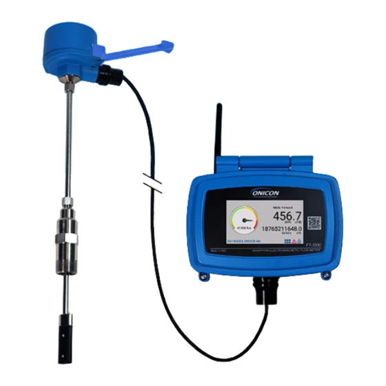
Summary of Contents for Onicon FT-3500
- Page 1 FT-3500 FT-3500 ELECTROMAGNETIC FLOW METER ELECTROMAGNETIC FLOW METER Installation and Operation Guide Installation and Operation Guide ONICON DOC-0006324 Rev.A...
- Page 2 • If the customer or any third party is harmed by the use of this product, ONICON assumes no responsibility for any such harm owing to any defects in the product which were not predictable, or for any indirect damages.
-
Page 3: Table Of Contents
MECHANICAL INSTALLATION ............................ 16 3.2.1 Installation Kit ..............................17 3.2.2 ONICON Standard Installation Hardware Kit ................... 17 3.2.3 ONICON Hot Tap Installation Hardware Kit ..................... 17 3.2.4 Customer Supplied Installation Hardware ....................18 3.2.5 Confirming the Stack Height .......................... 19 3.2.6 Installing Grounding Rings (non-conductive or lined pipes only)........... -
Page 4: Introduction
Death or permanent injury may result from accidents with these systems. This guide is the basic reference tool for all ONICON FT-3500 Electromagnetic Flow Meters. If you have not purchased all of the options, there will be references in this manual which are not applicable to your meter(s). -
Page 5: Typical Meter Installation
7. ONICON provided cable up to 200ft. Direct burial rated. 8. Order ONICON Installation kits separately. Installation kits vary based on pipe material and application. For installations in pressurized (live) systems, use “Hot Tap Installation Kit” and drill hole using a 1” wet tap drill. -
Page 6: Standard Features And Specifications
Removable orange terminal blocks for use with 18-22 AWG I/O SIGNALS Removable green terminal blocks for use with 18-22 AWG RS485 Removable green terminal blocks for use with 18-22 AWG RJ45 connector COMMUNICATION PROTOCOLS BACnet MS/TP, BACnet UDP/IP, MODBUS RTU, MODBUS TCP/IP ONICON Incorporated 727.447.6140 Page 6 onicon.com... -
Page 7: Additional Required Hardware
FCC: Part 15, Subpart B ADDITIONAL REQUIRED HARDWARE All ONICON insertion type meters can be installed and removed via a 1” or larger full port ball valve without system shutdown. The terms “Standard” and “Hot Tap” refer to the installation method of the isolation valve kit only. -
Page 8: Additional Hardware That May Be Required
ONICON provides grounding rings as an optional accessory. Grounding ring dimensional information and part numbers are listed below. For proper operation, grounding rings are required before and after the meter. -
Page 9: Grounding Probes
The downstream distance between the thermowell and flow meter should be at least five pipe diameters, leaving enough clearance to remove either sensor from the pipe without interference from the other sensor. ONICON Incorporated 727.447.6140 Page 9 onicon.com... -
Page 10: Thermowell Installation
Dry tap thermowells are for new construction or scheduled shutdown. The most common installation methods are shown below. Refer to Appendix A-1 for thermal insulator installations and Appendix A-2 for high temperature (>300°F) thermowell installations. Consult ONICON for special applications. NOTES 1. - Page 11 DO NOT OVER TIGHTEN THE POSITION CLAMPING NUT. If fluid leaks, do not attempt to correct by tightening this nut further. An internal o-ring seals the fluid. Contact ONICON for assistance in the event of a leak. ONICON Incorporated 727.447.6140 Page 11 onicon.com...
- Page 12 Rotating the thermowell as you slowly withdraw it through the valve will ensure that the lower tip is fully withdrawn and completely free of the valve. If resistance is felt when closing the valve, open valve fully and rotate the well as you pull it further out of the pipe. ONICON Incorporated 727.447.6140 Page 12 onicon.com...
-
Page 13: Unpacking
FT - 3500 ELECTROMAGNETIC FLOW METER SECTION 2.0: UNPACKING The FT-3500 sensor, remote display, and cable will be packed together in one box. All other installation hardware and peripheral devices will be packaged and shipped separately. IMPORTANT NOTE: Sensor and Remote Display are calibrated together and matched by serial number. -
Page 14: Installation, Removal & Adjustment
ONICON will be happy to assist with technical recommendations and to provide guidance by telephone (727-447-6140) or e-mail (techsupport@onicon.com). On-site field engineering, installation and service is also available at additional cost. - Page 15 FT - 3500 ELECTROMAGNETIC FLOW METER For Horizontal Pipe Position Meter CLEARANCE Anywhere in Upper REQUIRED FOR 240º (All Meters) INSTALLATION FT-3500 Series 30 - 40" depending on pipe size FLOW Downstream Upstream Available Straight Run (A) Minimum straight run required...
-
Page 16: Mechanical Installation
CAUTION ONICON insertion style flow meters must be installed through a valve assembly. Failure to do so negates the ability to remove the meter without shutting down and draining the system. It will also result in an excessive amount of stem protruding from the pipe. -
Page 17: Installation Kit
3.2.3 ONICON Hot Tap Installation Hardware Kit ONICON offers an alternative installation hardware kit when it is not practical to relieve pressure and drain the system. In this case, a 1¼” branch outlet, close nipple and 1¼” full port ball valve are installed first. Then, a hot tap drilling apparatus is used to drill a 1”... -
Page 18: Customer Supplied Installation Hardware
In these cases, it is important to confirm that the installation hardware is suitable for use with the flow meter provided by ONICON before it is installed. The installation must allow for sufficient overhead clearance to fully extract the meter and a full 1”... -
Page 19: Confirming The Stack Height
ONICON insertion flow meter stem lengths vary according to the pipe diameter and the height of the installation hardware stack. ONICON records the stack height dimension provided by the customer at the time of order entry, and the information is used to size the stem. For standard configuration meters, the dimension of the max stack height and the depth gauge is shown on the tag attached to the meter. -
Page 20: Installing Grounding Rings (Non-Conductive Or Lined Pipes Only)
(Please note that the straight run requirements shown above are only for locating the grounding rings with respect to the FT-3500 flow meter. The complete straight run requirements for this meter are found in Section 3.1 on page 15 of this manual.) 2. -
Page 21: Installing The Flow Meter
The clamping nut is not part of the sealing mechanism. Any leaks in this area indicate that the “O” ring is not sealing properly and you must contact ONICON for assistance. -
Page 22: Insertion Of The Meter
If unable to pierce the insulation jacket, you will have to adjust depth to account for the insulation thickness. ONICON Incorporated 727.447.6140 Page 22 onicon.com... -
Page 23: Removal Of The Meter
IMPORTANT NOTE Removal of the meter is the same for small pipe configuration meter installations. The clamping nut can be accessed with the alignment tool installed. ONICON Incorporated 727.447.6140 Page 23 onicon.com... -
Page 24: Wiring Connections
(Class II Power Supply) Required 24 V (+) 22-26 VDC, 25 W Max COMMON GROUND 20-28 VAC, 30 vA Max, 60 Hz STEP 1 Remote Sensor Connections PURPLE BROWN SHIELD SHIELD BLACK SHIELD YELLOW ORANGE ONICON Incorporated 727.447.6140 Page 24 onicon.com... -
Page 25: Signal Outputs
0-10V, 2-10V, 0-5V, 1-5V ANALOG (+) ANALOG Dry Contacts 4-20mA ANALOG (+) OUT 2 COM (-) Volume Scaled Output Directional Contact (Flow Version, FT-3500-1) Frequency Output for an ONICON Peripheral Energy Scaled Pulse Output (Flow and Energy FREQUENCY (+) Version, FT-3500-2) FREQUENCY (-) -
Page 26: Temperature Sensor Connection (For Energy Version Only)
REFERENCE (-) *Move Jumper J10 & J11 for 2W or 4W RTD SHIELD RTD Sensor vs. ONICON Solid State Sensor NOTE: Confirm the type of temperature sensor provided. The wiring on the left is for a TSP-RKP-XXXX and the wiring on the right is for TSP-OFR-XXX which is the most common temperature sensor. -
Page 27: Network Communications Outputs
Terminate if the meter is the LAST Network Communications Outputs device on the network. BACnet /IP or MODBUS TCP/IP RJ 45 BACnet MSTP or MODBUS RTU DO NOT USE NOTE: Do not connect shield to ground (GND) ONICON Incorporated 727.447.6140 Page 27 onicon.com... -
Page 28: Other Connections
Resistive load to Earth Ground Open to Earth Ground Move Jumper from O Position to I Position if a Dry Contact *ONICON calibration tables are created at Default position using Auxiliary Input is Needed for other position can mitigate noise Counts. -
Page 29: Signal And Power Wiring Connections
3.6.1 Earth Connection FT-3500 Electromagnetic Flow Meters are designed to detect microvolt signal levels at the electrodes located on the sensor head. These signals are generated as conductive fluids flow through the magnetic field generated by the meter. -
Page 30: Programming Menu
MulitUser Pulse Factor Date and Time Pulse Duration Year Units Back to Main Menu Month Hour Frequency Out Minute Frequency Max (Hz) Second Back Set Time Flow at Max Frequency (GPM) Meter Factor (PPG) ONICON Incorporated 727.447.6140 Page 30 onicon.com... - Page 31 The yellow section is 10-17ft/s. The red section is 17-20ft/s. Mode Indication: The FT-3500 will indicate the flow mode status based on the selection under Main Menu->Meter Mode->Mode. If bidirectional is selected, the main screen will show Forward vs Reverse flow depending on the direction of the measured flow.
- Page 32 Utility: The utility menu allows users to revert to factory settings and to register multiple users for meters utilized across several pipes. ONICON Incorporated 727.447.6140 Page 32 onicon.com...
- Page 33 Instances (BACnet Only): Provide a unique number for the meter in the trunk. Stop Bit (MODBUS Only): default to 1 Parity (MODBUS Only): Selectable as None, Even or Odd. Access this screen through Main Menu --> User Config --> Network ONICON Incorporated 727.447.6140 Page 33 onicon.com...
- Page 34 FT - 3500 ELECTROMAGNETIC FLOW METER For BACnet IP and MODBUS TCP/IP: Network Address: numerical label assigned to the FT-3500. Network Mask: Divide the Network address into the subnet and specify the network available. Gateway: Access point numerical configuration for data to...
- Page 35 Access this screen through Main Menu --> User Config --> Input/Output Analog Outputs: FT-3500 has two analog outputs (Terminal TB3-1 and TB3-2). Terminal TB3-1 is Output 1 and terminal TB3-2 is Output 2. Output Options: Energy, Energy Heating, Energy Cooling, Supply Temp, Return Temp, Delta Temp.
- Page 36 IO 1, IO2 or IO3 / Output: Close contact output for the Access this screen through Main Menu --> User FT-3500. Output Options can be configured to None, Config --> Input/Output --> Digital I/O Volume, Volume Forward, Volume Reverse, BTU Total Pulse...
- Page 37 FT - 3500 ELECTROMAGNETIC FLOW METER Frequency Out Settings: This feature is typically used if the FT-3500 is connecting to an ONICON peripheral such as SYS-10, SYS-20, SYS-1000 or D-100 via Meter Factor. The user can set the Frequency Max (Hz) and the Flow at MaxFreq (GPM) via the keypad.
- Page 38 Nonconductive Nonmagnetic Smooth Walled Pipe: has a smooth surface texture, and they are made from materials that do not conduct electricity or exhibit magnetic properties. For example, pipes with similar properties like PVC, PPR, or other plastic pipes. ONICON Incorporated 727.447.6140 Page 38 onicon.com...
- Page 39 The user can set Meter Mode to be Unidirectional (for a pipe with flow in one direction) or Bidirectional (for a pipe with flow in two directions). Sensor Type is set by ONICON and cannot be updated in the field.
- Page 40 Through the Alerts screen, the user can access information regarding active errors, alarms, and warnings. Please refer to Section 6.0 on pages 59-64 of this manual for the full list of warnings, alarms, and errors and their meanings. ONICON Incorporated 727.447.6140 Page 40 onicon.com...
- Page 41 High flow with noise (Check grounding) Raw I/O: The FT-3500 Raw Values screen will show the user the voltage of electrodes 1 and 2, the raw values for pulse and analog inputs/ outputs, and the current or resistance from the temperature sensors (if using the FT-3500 as an energy meter).
- Page 42 The signal connections screen will give the user the connection status of the meter’s electromagnetic sensors/coil, temperature sensors/ RTDs (if using as an energy meter), and transmitter output status. Note that flow is required for an accurate sensor connectivity status. ONICON Incorporated 727.447.6140 Page 42 onicon.com...
- Page 43 If the user wants the screen to always be illuminated, set the auto dim time to 0. ONICON Incorporated 727.447.6140 Page 43 onicon.com...
- Page 44 Date and Time: User can set the date and time of their ideal time zone and location. Set the time in a 24-hour format. The main display will be in a 12-hour format. ONICON Incorporated 727.447.6140 Page 44 onicon.com...
- Page 45 The “Restore” button will recover all preferences set from the factory. Mulituser / User Configurations: The FT-3500 allows the user to save up to 4 separate meter preferences. This feature can be utilized when a meter is used in multiple pipes. Once pipe configurations, I/O, and network configurations are set, the user can save the preferences via this screen.
-
Page 46: Start-Up & Commissioning
Please read these helpful hints before proceeding with the start-up and commissioning procedure on the next page. 1. ONICON flow meters are individually calibrated for a particular application. Be sure to verify the pipe size and location. -
Page 47: Start-Up And Commissioning
Refer to troubleshooting guide when readings are the flow rate displayed by the inconsistent. control system. End of standard start-up and commissioning. Please contact ONICON at +1 (727) 447-6140 with any questions. ONICON Incorporated 727.447.6140 Page 47 onicon.com... -
Page 48: Start-Up And Commissioning Worksheet
2-10, 1-5, 0-10 or 0-5VDC Signal _________VDC _________VDC _________VDC _________VDC (select one): _____________ _____________ _____________ _____________ Scaled output interval: _________GPM _________GPM _________GPM _________GPM Calculated flow rate: Flow rate displayed _________GPM _________GPM _________GPM _________GPM by control system: ONICON Incorporated 727.447.6140 Page 48 onicon.com... -
Page 49: Network Configuration
Shield wires must not be connected to the RS485 connector on the FT-3500. • The maximum number of devices allowed on an RS485 network segment without a repeater is 32. - Page 50 Check DC Voltage (set multimeter to DC) • • Earth Ground Normal reading: Less than 2.0 VDC Check DC Voltage (set multimeter to DC) • • Earth Ground Normal reading: Less than 2.0 VDC ONICON Incorporated 727.447.6140 Page 50 onicon.com...
- Page 51 FT - 3500 ELECTROMAGNETIC FLOW METER BACnet Protocol Implementation Conformance Statement Date: 01/03/2023 Vendor Name: ONICON Inc. Product Name: FT-3500 Product Model Number: FT-3500-1 and FT-3500-2 Application Software Version: 2.6.0 Firmware Revision: 1.8.0 BACnet Protocol Revision: 16 BACnet Standardized Device Profiles Supported (Annex L): ...
- Page 52 Indicating support for multiple character sets does not imply that they can all be supported simultaneously. ISO 10646 (UTF-8) IBM™/Microsoft™ DBCS ISO 8859-1 ISO 10646 (UCS-2) ISO 10646 (UCS-4) JIS X 0208 ONICON Incorporated 727.447.6140 Page 52 onicon.com...
- Page 53 , Gallons, or Ft Analog Value 29 Mode 2 Yesterday Volume Total Liters, M , Gallons, or Ft Analog Value 30 Mode 2 Last 30 Days Volume Total Liters, M , Gallons, or Ft ONICON Incorporated 727.447.6140 Page 53 onicon.com...
- Page 54 18 states that indicate hardware or functional failures Normal EEPROMFail I2CFail VelTblCrrpt PipCfgMssng GrnTtlCrrpt YrTtlCrrpt ElecDiffOOR MSV 0 Errors Elec0 D/C 10. Elec1 D/C 11. ElecBckwrds 12. CoilOpen 13. CoilShort 14. CoilOOR 15. EmptyPipe 16. BrdTempFail 17. 3.3VRailLow 18. RtcFail ONICON Incorporated 727.447.6140 Page 54 onicon.com...
-
Page 55: Troubleshooting Guide
Reading is too high or low • Verify pipe size. Contact ONICON if pipe size is different from calibration tag. • Verify that the meter is properly inserted into the pipe. •... -
Page 56: Earth Connections & Electrical Noise Reduction
5.4.1 Earth Connections & Electrical Noise Reduction Introduction FT-3500 electromagnetic flow meters are designed to detect microvolt signal levels at the electrodes located on the sensor head. These signals are generated as conductive fluids flow through the magnetic field generated by the meter. If enough random electrical noise is present at the electrodes, it can interfere with the flow signal measurement. - Page 57 Locate a better earth connection for the flow Pipe & fluid are not con- Poor earth connection High meter. If noise level is still too high, locate a nected to earth better earth connection for the pipe or fluid. ONICON Incorporated 727.447.6140 Page 57 onicon.com...
-
Page 58: Errors
If the error disappears, power cycle the unit to confirm if the error no longer exists. • If the error reappears, contact ONICON. RMA needed. The Meter could lost the memory. • If the error is no longer present after changing it to a common pipe, change the pipe configuration to the desired pipe configuration. - Page 59 If any cable is corrected during the continuity test, power on the unit and check the error, it should disappear. • If the cables are connected, contact ONICON. RMA need (possible bad stem) “Error Elec 1/2 Diff OutRange” Electrode 1 and 2 readings differ too greatly Perform the steps on the previous alarm.
- Page 60 If any cable is corrected during the continuity test, power on the unit and check the error, it should disappear. • If the cables are connected, contact ONICON. RMA needed. “Error Flow Wave Cfg Corrupt” Meter configuration corrupt Contact ONICON.
-
Page 61: Alarms
POTENTIAL ISSUE POSSIBLE SOLUTION “Alarm Max Velocity” The actual flow is greater than the volumetric Nonideal flow rate condition. Contact ONICON if a short flow rate at 20 ft/s high flow rate test is needed “Alarm High Flow” Meter has reached HW flow limit of 20 ft/sec, or •... -
Page 62: Warnings
• Verify configuraiton of Analog Input at BAS. • If problem persists, contact ONICON support “Warn AOUT 1 Communications Fail” Analog output controller hardware reports Contact ONICON. RMA needed communications failure - Analog Out port 1 “Warn AOUT 1 Timeout”... - Page 63 Check continuity along each Electrode 1 wire to verify wire connection between the sensor and transmitter. • Also, check Electrode 1 wiring for continuity between other wires, ground, or either body. If problem persists Contact ONICON support. ONICON Incorporated 727.447.6140 Page 63 onicon.com...
- Page 64 - port 3 • Check Pulse Factor, Pulse Duration, and Volume Unit on Digital I/O screen, and Pipe Config Settings screen. If the problem persists, contact ONICON support. “Warn Fact Defaults Corrupt” Factory defaults missing. (Factory Restore Update firmware on both the main board and feature can not be used.)
- Page 65 Update Procedure TechNote. “Warn SPI/I2C Transient Error” Transient error detected on meter internal Contact ONICON. RMA needed communication bus ONICON ONICON Incorporated • 11451 Belcher Road South • Largo, FL 33773 • USA (P) 727.447.6140 • sales@onicon.com • onicon.com...
Need help?
Do you have a question about the FT-3500 and is the answer not in the manual?
Questions and answers