
Related Manuals for Onicon Fox Thermal FT4X


Summary of Contents for Onicon Fox Thermal FT4X
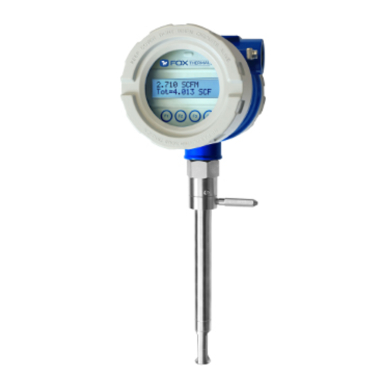
- Page 1 Fox Thermal THERMAL MASS FLOW METER & TEMPERATURE TRANSMITTER Model FT4X www.foxthermal.com | 399 Reservation Road Marina, CA. 93933 106796 Rev D...
- Page 2 Please note that Fox Thermal reserves the right to change and/or improve the product design and specification without notice. Fox Thermal FT4X Manuals: • Fox Thermal FT4X View™ Manual All Fox Thermal Manuals and software available in English only.
-
Page 3: Table Of Contents
Model FT4X Table Of Contents 1. Introduction Page 4 a. Quick Start Guide Page 4 b. Menu Trees Page 6 c. General Page 15 2. Installation (Mechanical) Page 18 a. Lateral Placement Page 19 b. Welding Branch Outlet Page 21 c. -
Page 4: Introduction
Model FT4X Quick Start Guide Use the table below as a guide while using the worksheet on the next page to record your notes. NOTE! Please read the entire quick-start procedure before beginning installation. Record inside diameter (ID). Ensure the actual pipe ID matches the pipe ID shown on the OUTER factory calibration certificate. - Page 5 Model FT4X Quick Start Guide Before powering on your meter, use this worksheet to record your notes. Serial Number: Serial Number: Serial Number: Serial Number: Item to verify What is the Pipe ID? ID = ID = ID = ID = Calculate the Upstream/ UP = UP =...
-
Page 6: Menu Trees
Model FT4X Introduction Fig. 1.1: FT4X Menu Tree - Main Menu Enter menu by scolling to display 4 and entering the password MAIN MENU I/O FLO DSP EXIT Display Menu, p. 10 Flow Menu 1, p. 8 I/O MENU I/O COM 420 EXIT Digital Output Menu, p. 7 SET 4‐20 mA Analog Outputs CH1 CH2 EXIT Communication mA=Temp Comm=Modbus None Temp Flow Modbus NXT OK NXT OK ... - Page 7 Model FT4X Introduction Fig. 1.2: FT4X Menu Tree - Digital Outputs and Input MAIN MENU I/O FLO DSP EXIT I/O MENU I/O COM 420 EXIT Set I/O OUT INP EXIT OUT= Pulse Inp= Not Used Not used Not used Pulse NXT OK Tot Reset NXT OK HiFloAlm LoFloAlm HiTempAlm LoTempAlm Pulse Alarm output High Flow Alarm Select 1 of 3 methods to scale the pulse output OUT= HiFloAlm NXT OK PULSE OUTPUT P/U U/P FEQ EXIT HiFloAlm=500 SCFM CHG OK...
- Page 8 Model FT4X Introduction Fig. 1.3: FT4X Menu Tree - Flow Menu 1 MAIN MENU I/O FLO DSP EXIT FLOW MENU 1 DGN UNT FM2 EXIT Flow Menu 2 Menu, p. 9 DIAGNOSTIC FLO UNT=SCFM SCFM SCFH SIM CAL‐V EXIT NXT OK NM3/H NM3/M KG/H KG/M KG/S TMP UNT=° F Deg F LBS/H Simulate Flow? Deg C NXT OK LBS/M YES NO LBS/S NLPH...
- Page 9 Model FT4X Introduction Fig. 1.4: FT4X Menu Tree - Flow Menu 2 MAIN MENU I/O FLO DSP EXIT FLOW MENU 1 DGN UNT FM2 EXIT FLOW MENU 2 GAS SPC PRM EXIT Parameters Level 2 Flow cutoff in selected units K fact = 0% Cutoff=12.5 SCFM CHG OK CHG OK Gas-SelectX Menu, p. 12 ® Pipe_id=4.026 In RESTORE DATABASE? Pipe id in inches or mm YES NO CHG OK Filter=0.8 Sec RESET CRC? Flow Filter in seconds CHG OK YES NO Min = 0.8, max = 10 HiFloAlm=0 SCFM CHG OK...
- Page 10 Model FT4X Introduction Fig. 1.5: FT4X Menu Tree - Display Menu MAIN MENU I/O FLO DSP EXIT DISP/TIME/PSW DSP LOG PSW EXIT Display 1 Line 1 FLo rate DSP1L1=FLo rate 24 Hour log=On PASSWD=1234 Total NXT OK NXT OK CHG OK Elps Display 1 Temp Line 2 Alarm Date/Time Review NXT FLo rate DSP1L2=Total Total NXT OK Elps Display 2 10/12/17 10:33 Temp Line 1 Alarm CHG OK...
- Page 11 Model FT4X Introduction Fig. 1.6: FT4X Menu Tree - CAL-V™ Menu MAIN MENU I/O FLO DSP EXIT FLOW MENU 1 DGN UNT FM2 EXIT DIAGNOSTIC MENU SIM CAL‐V EXIT CAL‐V MENU VER EXIT VERIFY CAL‐V? YES NO Choosing “Hold Value” will retain the last flow value while test is being performed. Hold Value Flo: Hold Value Go to zero NXT EXIT OK Take Control off‐line EXIT OK Verifying CAL‐V Please Wait Verifying CAL‐V 0.512 T=123 Displays a number value Displays the test’s during test count down timer CAL‐V=2.321 CAL‐V=0.259 CAL‐V=0.911 Fail OK Pass OK...
- Page 12 Model FT4X Introduction Fig. 1.7: FT4X Menu Tree - Gas-SelectX Menu ® MAIN MENU I/O FLO DSP EXIT The most recent list of available gases can be found on the Fox Thermal website: FLOW MENU 1 DGN UNT FM2 EXIT www.foxthermal.com/products/ft4x.php#gasSelectX FLOW MENU 2 GAS PRM EXIT GAS=O&G Mix Pure Gas NXT OK O&G Mix Pure Gas Be sure mixture equals 100%.
- Page 13 Model FT4X Introduction Fig. 1.8: FT4X Menu Tree - Log Menu 1 Enter Log Menu: Press F1 & F2 at the same time Press F4 to return to normal mode LOG MENU 1 Enter Log Menu: Press F1 & F2 at the same time LOG TOT ENG EXIT Press F4 to return to normal mode Press F1 to navigate up Press F2 to navigate down Press F4 to return to normal mode LOG MENU 1 LOG TOT ENG EXIT Day1=0 SCF 3124.6 SCFM Flow rate measured by the meter Display 10 NXT PRV EXIT csv = 0.3432 Volt Current Sense Voltage of sensor measurement circuit Press F1 to navigate up Log Menu 2, p. 14 Press F2 to navigate down Pulse=1234.5 cnt Digital control counts of Pulse output Press F4 to return to normal mode Display 11 mA_420=234 cnt Digital control count of 4‐20mA output...
- Page 14 Model FT4X Introduction Fig. 1.10: FT4X Menu Tree - Log Menu 2 Enter: Press F1 & F2 at the same time F3 & F4 pressed at the same time will Press F4 to return to normal mode initiate a "Total" reset LOGS MENU 1 LOG TOT ENG EXIT LOGS MENU 2...
- Page 15 Model FT4X Introduction Welcome Thank you for purchasing the Model FT4X Thermal Gas Mass Flow Meter from Fox Thermal. The FT4X is one of the most technically advanced flow meters in the world. Extensive engineering effort has been invested to deliver advanced features, accurate measurement performance and outstanding reliability.
- Page 16 Model FT4X Introduction instrument calibration data on every flow meter. Calibration files include details on process conditions, customer gas, line size and other information. All NIST-traceable equipment utilized for the calibration procedure is identified on the Calibration Certificate, which is sent with every flow meter.
- Page 17 Model FT4X Introduction Software Manual for data downloading instructions. Data that can be downloaded through FT4X View™ includes hourly and daily averages and totals. This data is saved for seven years as required by API 21.1. FT4X Functional Diagram An on-board 2 line x 16 character backlit LCD display shows flow rate, total flow, elapsed time, process gas temperature, and alarms.
-
Page 18: General
Model FT4X Installation Installation Scope This section describes how to install the Fox Thermal Model FT4X Flow Meter: For Insertion Types: 1. Determine lateral position on the pipe 2. Verify sensor installation depth 3. Determine sensor orientation in relation to sensor length and direction of flow 4. -
Page 19: Lateral Placement
Model FT4X Installation Instructions for Flow Meter Lateral Placement Install the Model FT4X flow meter so that it is far enough away from bends in the pipe, obstructions, or changes in line sizes to ensure a consistent flow profile. See Fig. 2.1 below for your meter type. - Page 20 Model FT4X Installation Tilt Installations - Moisture in the Gas or Condensation Tilt Installations - Moisture in the Gas or Condensation Tilted variations on installations help prevent moisture and condensation from forming Tilted variations on installations help prevent moisture and condensation from forming on the sensor and disrupting accurate flow measurement.
-
Page 21: Welding Branch Outlet
Model FT4X Installation Welding NPT Female Fitting to Pipe The probe of the FT4X must be installed perpendicular in the pipe to measure flow accurately. Use the following steps to ensure that the 1" NPT female fitting is correctly welded to the pipe. Directions: 1. -
Page 22: Installation Depth
Model FT4X Installation Installation Depth The installation depth of the sensor in the pipe is dependent on the pipe size. To get the most accurate reading, proper placement of the sensor window within the pipe is necessary. As shown in Fig 2.4, the end of the sensor window should be 0.73" (18.5 mm) past the center line of the pipe. -
Page 23: Orientation
Model FT4X Installation Rotating the Enclosure The Model FT4X enclosure has been designed to allow the enclosure to rotate for optimal viewing of the display. To rotate the enclosure, first loosen the two set screws near the Flow Direction Indicator. Then rotate the enclosure into the desired position and tighten the set screws. - Page 24 Model FT4X Installation Changing the Orientation of the FT4X Display The display can be rotated in 90° increments for optimum viewing of the screen. First, open the enclosure by unscrewing the enclosure cap and loosen the two captive screws to open the display assembly.
-
Page 25: Mounting Instructions
Model FT4X Installation Mounting Instructions - Compression Fittings The Model FT4X is mounted through a 0.781" hole and a 1-inch female NPT branch outlet in the customer's pipe. Insertion style flow meters are not designed for use in pipes smaller than 1½". -
Page 26: Retractor Installation
Model FT4X Installation Installation of a New Retractor Assembly 1. Remove collar clamp from probe using a 3/16" Hex Key. 2. Remove meter probe from retractor assembly and leave the ball valve open. Keep the collar spacer on the probe so it is not misplaced. 3. - Page 27 Model FT4X Installation 4. Carefully slide the probe through the retractor assembly and through the hole to see if there is interference by touching the pipe wall with the end of the probe on the far side or until the probe cannot go deeper.
- Page 28 Model FT4X Installation 5. Using the equation (L + D/2 + 0.73") from Figure 2.11, calculate the insertion depth and mark on the probe while measuring from the end of the probe. 6. The Retractor Clearance table of Figure 2.11 lists the space required to remove the meter from the retractor.
- Page 29 Model FT4X Installation 7. Insert probe back into the retractor to the depth mark and hand-tighten the compression fitting. Make sure collar spacer is in place on the probe. 8. Verify that flow direction indicator is in line with pipe and in the direction of flow. Fig.
-
Page 30: Wiring (Electrical)
Model FT4X Wiring Wiring Instructions To wire the FT4X connect the power and signal wires to the terminal blocks according to the label and instructions on the following pages. Fig. 3.1: FT4X Wiring Access Front Enclosure Cap Rear Enclosure Cap Unscrew the rear enclosure cap to access wiring Unscrew front enclosure cap to access the terminals for power, inputs/outputs, pulse,... - Page 31 Model FT4X Wiring Wiring Precautions • WARNING! - DO NOT OPEN THE ENCLOSURE WHEN ENERGIZED OR AN EXPLOSIVE ATMOSPHERE IS PRESENT. • All plumbing and electrical installations of flow meters must be in compliance with local codes, the end user’s best engineering practices, and manufacturer’s recommendations. •...
-
Page 32: Input Power
Model FT4X Wiring Power Input Requirements: 12 to 28VDC External DC power supply must provide 12 to 28VDC (10 to 30VDC full input power range) at 6 Watts minimum. (With 12VDC power, the FT4X can use up to 500mA. With 24VDC power, the FT4X can use up to 250mA.) A 20 Watt or greater power supply is recommended to ensure it can provide enough current under all temperature, ventilation, and power on conditions. -
Page 33: Signal Wiring And Hart Communication Option
Model FT4X Wiring 4-20mA Output and HART Comm. Wiring: Customer-Supplied Power Source (Recommended) Bring the wiring in through either conduit hub. Connect the 4-20mA flow rate, 4-20mA temperature, and HART communication option wiring as shown in the diagram below. Fig. 3.3: 4-20mA Output Wiring for Isolated Customer-Supplied Power Source FT4X Customer PLC or DCS +12 to 28VDC... - Page 34 Model FT4X Wiring 4-20mA Output and HART Comm. Wiring: Loop Power Provided by FT4X Bring the wiring in through either conduit hub. Connect the 4-20mA flow rate, 4-20mA temperature, and HART communication option wiring as shown in the diagram below. Fig.
- Page 35 Model FT4X Wiring Pulse/Alarm Output Wiring: Customer Supplied Power Source (Recommended) Bring pulse/alarm wiring in through either conduit hub. Connect the pulse/alarm wiring as shown in the diagram below. The pulse/alarm output is an open collector circuit capable of sinking a maximum of 20mA of current. Pulse or alarm selection is programmed using the display or FT4X View™.
-
Page 36: Pulse/Alarm Wiring (Optional Feature)
Model FT4X Wiring Pulse/Alarm Output Wiring: Power Provided by FT4X Bring pulse/alarm wiring in through either conduit hub. Connect the pulse/alarm wiring as shown in the diagram below. The pulse/alarm output is an open collector circuit capable of sinking a maximum of 20mA of current. Pulse or alarm selection is programmed using the display or FT4X View™. - Page 37 Model FT4X Model FT4X Wiring Switch Input Wiring A remote switch can be used to reset the Totalizer and elapsed time, if enabled in the programming settings. Connect the switch input wiring as shown in the diagram below. Fig. 3.7: Switch Input Wiring Customer PLC or DCS FT4X 0.75A...
-
Page 38: Rs485 Wiring
Model FT4X Model FT4X Wiring RS485 Wiring for Modbus RTU (RS485) Wiring connections are made as shown in the diagram below for Modbus communication. Termination Resistor Connect a termination resistor across the receive/transmit signals of the last device on the communication line. -
Page 39: Hart Handheld Wiring
Model FT4X Wiring HART 4-20mA Output Wiring: Handheld Communicator The 4-20mA current loop and HART modem connections are shown on p. 33 and p. 34. A handheld HART communicator can be connected to test points TP1 (+) and TP2 (-) with clip leads or to the 4-20mA terminal block. -
Page 40: Remote Wiring
Model FT4X Wiring Remote Wiring Remote wiring is only necessary when the remote sensor option has been ordered. Fig. 3.10: Remote Wiring Remote Wiring 3 X Port, Remote Cable, 8 Conductor, 3/4 " NPT Female Shielded, 100ft (30.48m) Max. Eight wire shielded cable required. The shielded cable should be run through a separate grounded steel conduit (no other cables or wires in the conduit). - Page 41 Model FT4X Wiring Fig. 3.11: Remote Sensor Wiring Electronics Enclosure Detail Remote Wiring Terminal Remote Enclosure Remote Wiring Terminals are accessed Located inside J-Box by opening the display panel hinged cover panel Remote Wiring Terminal Customer Wires Sensor Wires Cable Probe Sensor Wired By Fox Shield NOTE! Wire colors listed here represent the wire colors of cables supplied by Fox...
-
Page 42: Operation (Standard Operation)
Model FT4X Operation Start Up Sequence The program automatically enters the Run/Measure mode after power up. The screen will show the software version of the FT4X during power up. USB Interface The USB interface is a standard feature which allows communication with a PC to monitor readings and configure settings. - Page 43 Model FT4X Operation Measurement Mode Display Screens In the measurement mode, there are four different display screens (display 1, 2, 3 and a prompt screen to enter the programming mode). Two display screens are user programmable (refer to Display Setup p. 50). Scrolling through the display is accomplished by pressing the F1 or F2 key to view the next or previous screen.
-
Page 44: Programming
Model FT4X Model FT4X Operation Programming: Data Entry using the Display and Configuration Panel There are 2 basic types of menu entries: one for changing value or string and one for selecting from a selection list. To Change a Value or String : VALUE = 0.91234 Press CHG (F1) key to change the value, OK (F4) to accept the value. - Page 45 Model FT4X Model FT4X Operation Enter the correct password, then follow the instructions for changing a value as specified on page p. 44. The default Level 1 password is “1234”. If the wrong password is entered, the message “Wrong Password” will display and then return to the programming entry screen.
- Page 46 Model FT4X Operation 4 mA = 0 SCFM Enter the value for the 4mA and press OK (F4). NOTE! When the flow rate exceeds the programmed value for the 20mA set point, the analog output will stay at 20mA and an alarm code will be generated. NOTE! 4mA is normally set to 0.
- Page 47 Model FT4X Operation Pulse/alarm Output The Pulse/alarm feature can be accessed from the Main Menu, press I/O (F1). EXIT Press OUT (F1) to select the pulse output. The following screen will show: OUT = Pulse Press NEXT (F1) to cycle through output options until you have the selection for "OUT=Pulse" and press OK (F4).
- Page 48 Model FT4X Operation Entering data in Unit per Pulse: From the Pulse/alarm Output Menu, press U/P (F2) and the following screen will show: UNT/PLS = 0.5 Press CHG (F1) to change the setting and then OK (F4) to accept entry. The value entered is in unit per pulse (i.e.
- Page 49 Model FT4X Operation OUT = HiFloAlm Then press NXT (F1) to select the correct alarm and press OK (F4). Selections are: Not used Pulse HiFloAlm = High Flow Alarm LoFloAlm = Low Flow Alarm HiTempAlm = High Temperature Alarm LoTempAlm = Low Temperature Alarm System Alarm When the output is set to Alarm and there is no alarm condition, the output will be on (0 volts).
- Page 50 Model FT4X Operation Serial Communication Settings If RS485 Communication feature was purchased, the Serial communication settings can be programmed by pressing I/O (F1) key from the Main Menu. The screen will show: I/O MENU EXIT Press COM (F2) to select Serial communication. The screen may show: Comm=Modbus Options for serial communication are:...
- Page 51 Model FT4X Operation To Program Display Screens #1 & 2: From the Main Menu press DSP (F3) to select the display menu: DISP/TIME/PSW EXIT Press DSP (F1) key. The display will show: DSP1L1 = Flo rate These are the selections for the display #1 line #1. Selections are: Flo rate = Flow rate Total = Total mass or volume...
- Page 52 Model FT4X Operation Reviewing and Enabling Date/Time for 24 Hour Logs and Contract Time: The 24-Hour Log should be enabled and set to the local date/time at the commission site to make full use of the Logs feature on the FT4X. The Contract Time setting allows the user to isolate the start time for recording daily flow totals.
- Page 53 Model FT4X Operation Press CHG (F1) to set the month value 1-12 (January = 1, October = 10): Month Set = MM Press OK (F4) to set the month value. Press CHG (F1) to set the day value 1-31: Day Set = DD Press OK (F4) to set the day value.
- Page 54 Model FT4X Operation The screen will show: MM/DD/YY HH:MM:SS Press OK (F4) to set the 24-Hour Clock as displayed and move to the Contract Time menu. NOTE! Contract Time will only be set if the 24 Hour Log has been selected to be "On". The following screens will cycle through hour and minute to set the Contract Time in the 24- Hour Clock format: HH:MM.
- Page 55 Model FT4X Operation Contr time = HH:MM Press OK (F4) to exit to the Display Menu. Password There are two user level passwords, only Level 1 is programmable and gives access to all the normal settings. The second password is used to allow access to calibration settings. Default Level 1 password is “1234”, and Level 2 password is “9111”.
- Page 56 Model FT4X Operation Units Settings Menu This menu is used to set the units for flow, temperature, and pressure as well as the setting of reference temperature and reference pressure. These values will be set at Fox Thermal using information supplied by the customer. These values can be changed to match a new application.
- Page 57 Model FT4X Operation Temperature Units After pressing OK (F4) to accept the Flow unit the display will prompt for the temperature unit setting: TMP UNT= ° F Press NXT (F1) to change selection and OK (F4) to accept. Selections for Temperature units are: °C or °F Reference Temperature After pressing OK (F4) to accept the temperature unit setting, the display will prompt for temperature reference in selected unit.
- Page 58 Model FT4X Operation Reference Pressure After the pressure unit selection is made, the display will show a menu to enter the reference pressure: PresRef= 14.7 Press CHG (F1) to change it and OK (F4) to accept. Accessing Flow Parameters and Alarm Settings This is the menu used to set various flow parameter values.
- Page 59 Model FT4X Operation Programming Flow Parameters Flow Cutoff The first parameter is Flow Cutoff: CUTOFF = 2.0 SCFM Enter the value for the flow cutoff and then press OK (F4). When the flow rate falls below the flow cutoff, the flow meter will display a flow value of zero. Pipe Diameter To set the pipe Diameter Pipe_id = 3.068 In...
- Page 60 Model FT4X Operation High Flow Rate Alarm This is the upper flow limit alarm value that can be associated with the alarm output. An alarm code is generated when the flow value exceeds this limit. If no alarm is needed, set this value to zero.
- Page 61 Model FT4X Operation Low Temperature Alarm This is the lower temperature limit alarm value that can be associated with the alarm output. An alarm code is generated when the temperature value is below this limit. If no alarm is needed, set this value to zero. To set the parameters for a high temperature alarm, press CHG (F1): LoTmpAlm = 20 F Press OK (F4) to accept the value.
- Page 62 Model FT4X Operation Press YES (F1) to continue. FloSim = 0 SCFM Enter the value and then press OK (F4). NOTE! Enter zero to disable this feature. Simulate Temp? Press YES (F1) to continue. TmpSim = 0 C Enter the value and then press OK (F4). Enter zero to disable this feature. ENABLE SIM? Press YES (F1) to start the simulation mode, otherwise press NO (F4).
- Page 63 Model FT4X Operation The K Factor parameter is accessed from the “Flow Menu 2” menu by entering a Level 2 password “9111” and pressing the SPC key (F2). FLOW MENU 2 EXIT The following screen will be displayed: K fact=0% Press CHG (F1).
- Page 64 Model FT4X Operation Reset CRC If the NVRAM CRC check fails (Error Code 36), the programmed settings values will need to be verified and corrected before clearing the error. Call Fox Thermal Customer Service if you need assistance. RESET CRC? Press YES (F1) ONLY if you want to reset the CRC and generate a new CRC value.
- Page 65 If the CAL-V™ test does not produce a "PASS" result, refer to "CAL-V™ Test Results" on page 67. NOTE! If the CAL-V™ test is performed using the Fox Thermal FT4X View™ Software, at the completion of the test, a CAL-V™ Certificate may be printed for a record of the test.
- Page 66 Model FT4X Operation Performing the CAL-V™ Calibration Validation Test NOTE! The FT4X will stop measuring flow when performing this test. Press FLO (F2) from the Main Menu. The display will show: FLOW MENU 1 EXIT Press DGN (F1). The display will show: DIAGNOSTIC MENU CAL-V EXIT...
- Page 67 Model FT4X Operation Press YES (F1) to continue. Process Stable? EXIT WARNING! If you are using closed loop control, the system needs to be taken off-line during the test. Press OK (F4) to start CAL-V™. CAL-V™ test screen: Verifying CAL-V y.yyy T=xx This test takes about 3 minutes (200 seconds).
-
Page 68: Gas-Selectx
Model FT4X Operation Gas-SelectX Available Gases and Gas Mix Menus ® This menu allows the user to select a gas or gas mix from a pre-calibrated list of gases/gas mixtures available in the Fox Thermal Model FT4X flow meter. When entering the FT4X gas menu the user will have three choices: 1. - Page 69 Model FT4X Operation NOTE! For the latest gas and gas mix menu, visit the Fox Thermal Website: www.foxthermal.com After installing your FT4X flow meter, power up the device. When the meter finishes initializing, it will begin to monitor flow in the assigned gas and flow units. Accessing the Gas-SelectX Gas Selection Menu Feature ®...
- Page 70 Model FT4X Operation In the Pure Gas menu, the user can choose from a list of 11 pure gases. The Mix menu is used for programming a specific mixture of gases. The O&G Mix menu is used for programming a specific mixture of common gases found in the Oil &...
- Page 71 Model FT4X Operation Methane=30.5% To set the percentage of methane in the gas mix, press UP (F1) or DN (F2) to choose the first digit of the percentage. Press NXT (F3) to move to the next digit in the percentage and then use UP (F1) or DN (F2) again to choose the next digit of the percentage.
-
Page 72: Data Logger
Model FT4X Logs Logs Introduction The data logger is internal to the model FT4X flow meter and includes separate hardware from the main flow meter electronics including battery-backed microprocessor, memory, real-time clock (RTC) and firmware. The RTC maintains accurate time when power is off to the flow meter. - Page 73 Model FT4X Logs Displaying Data Log Records From the normal operating mode, press F1 & F2 keys at the same time: LOGS MENU1 EXIT F1 (LOG) will enter the Logs Menu 2: • The Gas or Gas Mix can be viewed here •...
- Page 74 Model FT4X Logs Viewing the Gas/Gas Mix From the Logs Menu 1, choose F1 (LOG) to enter Logs Menu 2: LOGS MENU2 EXIT Press F1 (GAS) to view the current gas, gross heating value, and density. If a pure gas is chosen, the gas will be listed with a value of 100%.
- Page 75 Model FT4X Logs Viewing the Meter's Configuration The meter's configuration settings include the flow units, temperature units, pressure units, 4-20mA output settings, alarm settings, reference pressure, reference temperature, K-Factor, flow cutoff, pipeID, filter, the meter's serial number, the firmware version, and the release date of the meter's firmware.
- Page 76 Model FT4X Logs Viewing the Most Recent Calibration Validation Test Data The meter's display will show the two (2) most recent logs of data for the CAL-V™ Calibration Validation tests that were performed on the meter. From the Logs Menu 2, choose F3 (VAL) to view the meter's configuration screens. LOGS MENU 2 EXIT The most recent test value data will be displayed first:...
- Page 77 Model FT4X Logs Viewing 24-Hour Daily Totals From the Logs Menu 1, choose F2 (TOT) to enter the 24-hour Daily Total Log: LOGS MENU1 EXIT The first screen will show the most recent, Day 1 total: Day1=0SCF Press F1 to navigate up through the displays. EXIT Press F2 to naviagte down through the displays.
- Page 78 Model FT4X Logs Viewing the Engineering Screens From the Logs Menu 1, choose F3 (ENG) to enter the Engineering Screens. LOGS MENU1 EXIT There are ten (10) screens (Displays 10-19) to view meter data: • Display 10 - flow rate measured by the meter, CSV of the sensor measurement circuit. •...
-
Page 79: Communication Protocols
Communications: Modbus Scope This portion of the manual describes the Modbus implementation using RS485 serial communication physical layer for the Fox Thermal FT4X Mass flow meter based on the Modicon Modbus Protocol (PI-MBUS-300 Rev. J). Modbus Protocol Modbus Protocol is an application layer messaging protocol that provides client/sever communications between devices. -
Page 80: Modbus Rtu (Rs485)
Model FT4X Communications: Modbus Modbus Function Codes Supported by the FT4X The FT4X supports the following commands: 1) Command 03: Read holding registers 2) Command 04: Read input register. 3) Command 06: Preset single register 4) Command 16: Preset multiple registers (limited to gas percentage register pairs) Read Holding Registers (command 03) This command reads the basic variable from the FT4X and has the following format: Request:... - Page 81 Model FT4X Communications: Modbus Table 5.1: FT4X Modbus Holding Registers Modbus Data Type Description Units Register 40001 32-bit int LSW Flow User selected 40002 32-bit int MSW 40003 32-bit int LSW Flow Total User selected 40004 32-bit int MSW 40005 32-bit int LSW Temperature Tenths of user selected...
- Page 82 Model FT4X Communications: Modbus Table 5.1: FT4X Modbus Holding Registers (cont'd) Modbus Data Type Description Units Register 40039 Reserved 40040 Reserved 40041 Reserved 40042 Reserved 40043 Reserved 40044 32-bit int LSW Reserved for Current time: year portion Years 40045 32-bit int MSW 40046 32-bit int LSW Reserved for Current time: month portion...
- Page 83 Model FT4X Communications: Modbus Read Input Register (Status, Command 04) This command is used to report the status information. Request: <Meter Address> <Command code=04> <Register address =0> <Register address =0> <Register count =0> <Register count =1> <CRC high> <CRC low> Response: <Meter Address>...
- Page 84 Model FT4X Communications: Modbus Preset Single Register (Command 06) This command is used to perform miscellaneous functions such as clearing the totalizer and elapsed time. The register address is Modbus=40018 and the data to write is described in table 5.1. Request: <Meter Address>...
- Page 85 Model FT4X Communications: Modbus In the following tables: S0 – S23 are the significand bits from least to most significant. E0 – E7 are the exponent bits from least to most significant. Sign is 1 if the number is negative, and 0 if the number if positive. Lower numbered register S15 S14 S13 S12 S11 S10 S9 Higher numbered register...
- Page 86 Model FT4X Communications: Modbus The message byte stream will be (bytes on the same line are sent leftmost first): <0x01> Address = 1 <0x10> function = write multiple registers <0x00> <0x39> start index = fifty seven, meaning register 40058 <0x00> <0x22 register count = 34 (holding seventeen 32-bit floating point values) <0x44>...
- Page 87 Model FT4X Communications: Modbus Select Record (command 06, Preset Register, Modbus Address 40032) This command is used to select a 24 hour record that is going to be read from the data log buffer using command 03 Address register = 40032 Data = xx.
- Page 88 Model FT4X Model FT4X Communications: Modbus Clear Data Log (command 06, Preset Register, Modbus Address 40213) This command is used to clear all records in the log. Address register = 40213 Data = 0x57. Request: <Meter Address> <Function code=06> <Register address high=0x00> <Register address low=0xd4>...
- Page 89 Model FT4X Model FT4X Communications: Modbus Baud=9600 Press NXT (F1) repeatedly until the correct selection is shown then press OK (F4) to accept the setting. Selections are: 115200 9600 76800 4800 57600 2400 38400 1200 19200 Parity=EVEN Press NXT (F1) repeatedly until the correct selection is shown and then press OK (F4) to accept the setting.
- Page 90 Model FT4X Model FT4X Communications: Modbus Selecting FT4X Gases and Gas Mixes Modbus register 40057 selects the gas type, which may be a pure gas (plus NAESB natural gas composition), custom gas mix, or custom oil & gas mix. Register 40057 will read zero, and register 40056 will read the gas selection that was chosen.
-
Page 91: Hart With Ddl
Model FT4X Model FT4X Communications: Modbus 40064 32-bit float LSW Air percentage Percent (31.4 = 31.4%) 40065 32-bit float MSW 40066 32-bit float LSW Argon percentage Percent (31.4 = 31.4%) 40067 32-bit float MSW 40068 32-bit float LSW Propane percentage Percent (31.4 = 31.4%) 40069 32-bit float MSW... - Page 92 Model FT4X Communications: HART Scope The Fox Thermal Model FT4X transmitter complies with HART Protocol Revision 7.1. This section of the manual specifies all the device-specific features and documents HART Protocol implementation details (e.g., the Engineering Unit Codes supported). The functionality of this Field Device is described sufficiently to allow its proper application in a process and its complete support in HART-capable Host Applications.
- Page 93 Model FT4X Communications: HART Process Flow Rate 4-20mA Analog Output The 4-20mA output of the FT4X HART represents the process flow rate measurement, linearized and scaled according to the configured range of the instrument. This output corresponds to the Primary Variable. HART Communication is supported on this loop. The 4-20mA output of the FT4X should be configured for flow rate when using HART.
- Page 94 Model FT4X Communications: HART Set Bus protocol for HART: Comm=HART Press NXT (F1) until HART is selected as shown and then press OK (F4) to accept the setting. NOTE! Power cycle is required for the new settings to take effect. Dynamic Variables Four Dynamic Variables are implemented.
- Page 95 Model FT4X Communications: HART Additional Device Status (Command 48) Command #48 returns 2 Device-Specific Status bytes of data, with the following status information: These bits are set when an alarm or error condition is present. The bit automatically clears when the condition returns to its normal state. Byte Meaning Class...
- Page 96 Model FT4X Communications: HART Common-Practice Commands, Unsupported Commands Burst Mode - This device does not support Burst Mode. Catch Device Variable - This device does not support Catch Device Variable. Device-Specific Commands - No Device-Specific commands are implemented. Modes Fixed current mode is implemented, using Command 40. This mode is cleared by power loss or reset.
- Page 97 Model FT4X Maintenance: Precautions PRECAUTIONS WARNING! BEFORE ATTEMPTING ANY MAINTENANCE, TAKE THE NECESSARY SAFETY PRECAUTIONS BEFORE REMOVING THE PROBE FROM THE DUCT ( EXAMPLE: PURGE LINES OF TOXIC AND/OR EXPLOSIVE GAS, DEPRESSURIZE, ETC... ) . WARNING! EXPLOSION HAZARD. DO NOT REMOVE OR REPLACE COMPONENTS OR FUSES UNLESS POWER HAS BEEN SWITCHED OFF WHEN A FLAMMABLE OR COMBUSTIBLE ATMOSPHERE IS PRESENT.
-
Page 98: Maintenance
Model FT4X Maintenance: General Broken or Damaged Probe If the sensor is broken or damaged, the probe and electronics must be returned to the factory. A new sensor will be installed and calibrated. Refer to "Returning Your Meter" on p. 124. Flow Calibration and Calibration Validation To ensure high accuracy of your Model FT4X Flow Meter, Fox Thermal provides a full NIST traceable calibration. -
Page 99: Safe Removal Of Meter From Retractor
Model FT4X Maintenance: Retractors Instructions for Removing and Inserting the Meter from a Pressurized Pipe using the Retractor WARNING! Possible injury or damage to equipment may occur if the retractor is not used correctly. Please read the following instructions carefully prior to using the retractor. - Page 100 Model FT4X Model FT4X Maintenance: Retractors Figure 6.1 Compression Nut, 1 ⅛" Wrench Compression Fitting, 1 ¼" Wrench Step 2 - Remove the Probe from the Retractor Body 5. After removing the probe from the flow stream (#1-4 on previous page), slowly loosen the compression fitting (see figure 6.2), until the pressure in the retractor is relieved.
- Page 101 Model FT4X Model FT4X Maintenance: Retractors Figure 6.2 COLLAR SPACER COLLAR CLAMP COMPRESSION NUT COMPRESSION FITTING BALL VALVE How to Insert the Probe into the Flow Stream (Valve closed, System Pressurized) 1. Carefully, slide the probe into the retractor. 2. Install the collar clamp just below the collar spacer, and tighten it in place on the probe. Slide the probe back out of the retractor until the cable is straight and taut.
- Page 102 Model FT4X Maintenance: Retractors Figure 6.3 COLLAR SPACER COLLAR CLAMP COMPRESSION NUT COMPRESSION FITTING BALL VALVE NOTE! At a maximum system pressure of 150psig, the force required to push the probe in place to tighten the compression Nut will be approximately 66 lbs. 3.
- Page 103 Model FT4X Maintenance: Retractors Figure 6.4 COMPRESSION NUT & FERRULES COMPRESSION FITTING 5. Secure the probe in place by tightening the compression nut with a 1 ⅛" wrench and a 1 ¼" wrench on the compression fitting. See p. 25 of the manual for detailed instructions to tighten the compression nut.
-
Page 104: Troubleshooting
Model FT4X Maintenance: Troubleshooting Troubleshooting CAUTION! The electronics and sensor supplied by Fox Thermal are calibrated as a single precision mass flow meter. Interchanging sensors will decrease the accuracy of the flow meter. If you experience any problem with your Model FT4X Flow meter, call Fox Thermal Customer Service Department, Technical Assistance at (831) 384-4300. - Page 105 Model FT4X Maintenance: Troubleshooting Problem Possible Cause(s) Action(s) Display Error 1. Loose or damaged 1. Visual inspection. ribbon cable 2. Return the meter or display for repair. 2. Damaged electronics 3. Operate meter between -20 to 70°C 3. Ambient temperature Flow measure- 1.
- Page 106 Model FT4X Model FT4X Maintenance: Installation Problems Installation Problems The following is a summary listing of problems that may be encountered with the installation of the FT4X Thermal Mass Flow Meter. 1. Improper wiring connections. Refer to Figures 3.1 to 3.11 and "Wiring Precautions" in Wiring section (p. 30) for further guidance.
- Page 107 Model FT4X Model FT4X Maintenance: Alarm Codes Alarm Codes Information to diagnose alarm codes is on p. 7 and p. 9 under the Menu Tree section. Enter password (9111) and follow the block diagram to get to the section affected by the error code. Alarm Reason Action...
-
Page 108: Appendices
Model FT4X Appendices Performance Specs Flow Accuracy: Insertion Meter: Air: ±1% of reading ±0.2% of full scale Other gases: ±1.5% of reading ±0.5% of full scale Accuracy specification applies to customer's selected flow range Maximum range: 15 to 60,000 SFPM (0.07 to 280 NMPS) Minimum range: 15 to 500 SFPM (0.07 to 2.4 NMPS) Straight, unobstructed pipe requirement Insertion Meters: 15 diameters upstream;... - Page 109 Model FT4X Appendices Operating Specs (cont'd) Temperature: DDC-Sensor™: -40 to 250°F (-40 to 121°C) Enclosure: -40 to 158°F (-40 to 70°C)* Remote Sensor Enclosure: -40 to 158°F (-40 to 70°C) *NOTE! Display dims below -4˚F (-20˚C), function returns once temperature rises again. Flow Velocity Range: 15 to 60,000 SFPM (0.07 to 280 NMPS) Turndown: up to 1000:1;...
- Page 110 Model FT4X Appendices Input Power: 12 to 28VDC, 6 watts max. Full Input Power Range: 10 to 30VDC. A 20 Watt or greater power supply is recommended to power the FT4X. Class I Equipment (Electrical Grounding Required for Safety). Installation (Over-voltage) Category II for transient over-voltages. Inputs/Outputs: 4-20mA Channel 1: •...
-
Page 111: Agency Approvals
Model FT4X Appendices Agency Approvals CE: Approved EMC Directive; 2014/30/EU Electrical Equipment for Measurement, Control and Lab Use: EN61326-1:2013 Pressure Equipment Directive: 2014/68/EU Article 13 Weld Testing: EN ISO 15614-1 and EN ISO 9606-1, ASME B31.3 FM (FM17US0061X) and FMc (FM17CA0032X): Approved Class I, Division 1, Groups B,C,D;... -
Page 112: Dimensions
Model FT4X Appendices Fig. 7.1 Insertion Meter with Retractor Dimensions Measurements shown in inches (millimeters). (206) (117) (99) 7.9±.2 (201±5.0) 2X 3/4" NPT, FEMALE "HH" 9.3±0.3 "LL" (236±7.6) Ø.75 PROBE (Ø19.0) .73" (18.5) DIMENSIONAL Table 7.1 Insertion Meter with 316 stainless steel probe Dimension “LL”... - Page 113 Model FT4X Appendices Fig. 7.2 Remote Insertion Meter with Retractor Dimensions Ø3.6 (Ø91) (206) (112) (117) (51) REMOTE (99) ENCLOSURE 7.2±.2 (183±5) (132) ELECTRONICS ENCLOSURE 2X 3/4" NPT, FEMALE "HH" CONDUIT, 3/4", METAL 9.3±0.3 "LL" 236±76 SHIELDED CABLE, 8-CONDUCTOR, 100FT (30.48m) MAX. Ø...
- Page 114 Model FT4X Appendices Fig. 7.3 Remote Mounting Kit Dimensions SIDE VIEW BRACKET 2x U-BOLT W/NUT JAM NUT SEE ADAPTER DETAIL PROJECTIONS ADAPTER Ø2.38 2 IN. PIPE WASHER THREADS ADAPTER DETAIL FRONT VIEW FT4X ENCLOSURE 2.81 4x Ø.344 2.81 MOUNTING HOLE DETAIL...
- Page 115 Model FT4X Appendices Fig. 7.4 Insertion Meter Dimensions (206) (117) (99) 7.9±.2 (132) (201±5) 2X 3/4IN. NPT, "HH" FEMALE "LL" (18.5) Table 7.4 Insertion Meter with 316 stainless steel probe Probe Size Probe Size Dimension “LL” ± .01 Dimension "HH" ± .01 [model code] [inches] [inches / millimeters]...
- Page 116 Model FT4X Appendices Fig 7.5: Insertion Remote Meter Dimensions Ø3.6 (Ø91) (206) (112) (117) (51) REMOTE (99) ENCLOSURE 7.2±.2 (183±5) (132) "HH" ELECTRONICS ENCLOSURE 2X 3/4" NPT, FEMALE "LL" CONDUIT, 3/4", METAL SHIELDED CABLE, .73" 8-CONDUCTOR, (18.5) 100FT (30.48m) MAX. Table 7.5 Insertion Remote Meter with 316 stainless steel probe Probe Size Probe Size...
- Page 117 Model FT4X Appendices Fig. 7.6 Inline Meter with 316 Stainless Steel Flow Body and NPT End Connections Dimensions (206) (117) (109) 2x 3/4 inch NPT Female (132) “H” 2x NPT Male Thread “L” Table 7.6 Inline Meter with 316 Stainless Steel Flow Body and NPT End Connections Body Size Body Size Dimension “L”...
- Page 118 Model FT4X Appendices Fig 7.7: Inline Remote Meter with 316 Stainless Steel Flow Body and NPT End Connections Dimensions (91) (112) (51) (117) (114) (132) “HH” Remote Cable, 8 Conductor, Shielded, 100FT Max. 2x NPT Male Thread “L” Table 7.7 Inline Remote Meter with 316 Stainless Steel Flow Body and NPT End Connections Body Size Body Size...
- Page 119 Model FT4X Appendices Fig. 7.8 Inline Meter with 316 Stainless Steel Flow Body and 150lb RF Flange End Connections Dimensions (206) (109) (117) 2x 3/4 inch NPT Female (132) “H” “L” 2X Flange, Raised Face, ANSI B16.5, 316 SST Table 7.8 Inline Meter with 316 Stainless Steel Flow Body and 150lb RF Flange End Connections Dimensions Body Size Body Size...
- Page 120 Model FT4X Appendices Fig 7.9: Inline Remote Meter with 316 Stainless Steel Flow Body and 150lb RF Flange End Connections Dimensions (91) (112) (51) (117) 2X 3/4 " NPT, (114) Female (132) “HH” Remote Cable, 8 Conductor, Shielded, 100FT Max. “L”...
- Page 121 Model FT4X Appendices Fig. 7.10 Inline Meter with 316 Stainless Steel Flow Body and 300lb RF Flange End Connections Dimensions (206) (117) (109) 2x 3/4 inch NPT Female (132) “H” 2X FLANGE, RAISED FACE, “L” ANSI B16.5, 316 SST Table 7.10 Inline Meter with 316 Stainless Steel Flow Body and 300lb RF Flange End Connections Dimensions Body Size Body Size...
- Page 122 Model FT4X Appendices Fig 7.11: Inline Remote Meter with 316 Stainless Steel Flow Body and 300lb RF Flange End Connections Dimensions (91) (112) (51) (117) (114) 2X 3/4 " NPT, Female (132) “HH” Remote Cable, 8 Conductor, Shielded, 100FT Max. “L”...
-
Page 123: Warranty
Model FT4X Appendices Warranty (a) Fox Thermal Instruments, Inc. (FOX) warrants that the products furnished under this Agreement will be free from defects in material and workmanship for a period of one year from the date of shipment. The customer shall provide notice of any defect to FOX, within one week after the Customer’s discovery of such defect. -
Page 124: Returning Your Meter
Model FT4X Appendices Returning Your Meter The Fox Thermal Customer Service Department (PH: 831- 384-4300 or FAX: 831-384-4312) can help you through the process of returning a meter for service. If it becomes necessary to return a Fox Thermal flow meter for service or recalibration, please follow these steps: 1. - Page 125 Model FT4X Appendices What to expect while your meter is being serviced Depending on the type of service required when returning your Fox Thermal meter, there are varying turnover times for servicing a meter. The average time needed to service the meter is 7-10 days (not including shipping or peak production times).
-
Page 126: Definitions
Model FT4X Definitions Glossary of Terms and Definitions American Wire Gauge Normal Liter Bara Bar absolute NLPH Normal Liter per Hour Contact NLPM Normal Liter per Minute Calibration Normal cubic Meter Change NM3/H Normal cubic Meter per Hour Communication NM3/M Normal cubic Meter per Minute Current Sense Voltage National Pipe Thread... -
Page 127: Index
Model FT4X Index Index Access to Electronics, p. 30 Power Input Wiring, p. 32 Alarm Codes, p. 107 Preventative Maintenance, p. 98 Alarm wiring, p. 36 Product Description, p. 15 Analog 4-20mA output, p. 45 Programming Breakage or Damage of Probe, p. 99 Analog 4-20mA Output, p. - Page 128 Wiring Definition of Terms Troubleshooting Tips NOTE! is used for Notes and Information WARNING! is used to indicate a hazardous situation which, if not avoided, could result in death or serious injury. CAUTION! is used to indicate a hazardous situation which, if not avoided, could result in minor or moderate injury.
Need help?
Do you have a question about the Fox Thermal FT4X and is the answer not in the manual?
Questions and answers