
Subscribe to Our Youtube Channel
Related Manuals for KanexPro HDSC71D-4K


Summary of Contents for KanexPro HDSC71D-4K
- Page 1 HDSC71D-4K HDSC71D-4K 4K Multi-input 7x2 Presentation Scaler Switcher User Manual v0.5...
- Page 2 HDMI source devices. When connected to the presentation system just click-to-show the content instantly on to the 4K display. The HDSC71D-4K optimizes the way we do video collaboration and presentations. These 4K-HDCLICKERs product brings together people, space, and information to amplify collaboration, and help distributed teams accelerate innovation while displaying their content one at a time directly from laptops, DisplayPort and HDMI based devices.
- Page 3 HDSC71D-4K CONTENTS Getting Started ................................ 5 Panel Layout ................................ 5 Front Panel ............................... 5 Rear Panel ................................ 6 IR Remote Control Unit ............................7 Button layout ..............................7 Power Cord and Adapter ..........................8 HDMI/DP Cable Switcher ........................... 8 Installation ................................9 How to Connect the 4K Multi-format Presentation Scaler Switcher ............
- Page 4 HDSC71D-4K EDID upload and Download ........................40 EDID Names ..............................42 EDID commands list .............................42 WEB Setting ...............................49 General Settings ............................50 Advanced Settings ............................54 Other ..................................58 Factory Reset Button ............................58 F/W Update ...............................58 Electrical Parameters ............................61 Relative Products Series: ..........................63 Version log:...
-
Page 5: Getting Started
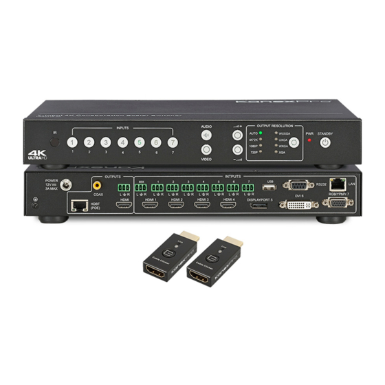
HDSC71D-4K Getting Started Panel Layout Front Panel Name Description IR Receive Window IR receive sensor, receives the IR signals from the IR remote. Press the buttons 1~7 to select the corresponding video or Input Buttons and Indicator audio input. The indicators mean the corresponding status of the video or audio input. -
Page 6: Rear Panel
HDSC71D-4K Rear Panel Name Description Connect the original AC-DC power adapter to this receptacle. DC Power Connector Connect the included AC power cord to the original power adapter connect the plug to an accessary AC-DC power adapter. Analog Audio 8 channel analog audio output, Connect a 3.5mm mini-stereo cable from this Output jack to the line in jack of a multimedia system. -
Page 7: Ir Remote Control Unit
HDSC71D-4K IR Remote Control Unit utton layout Name Description Press this button to power-ON or power-OFF Power the 4K Multi-format Presentation Scaler Switcher. Press "1-7" buttons to select the corresponding video input or audio Input 1-7 input. Press Video button and press the "1-7" buttons to select the corresponding video input. -
Page 8: Power Cord And Adapter
HDSC71D-4K Press this button to increase or decrease program audio output Volume Up & Down volume. Press this button to Mute or UnMute the 4K Multi-format Presentation Mute Scaler Switcher audio output. Press this button to change the 4K Multi-format Presentation Scaler Resolution Switcher HDMI output resolution. -
Page 9: Installation
Installation How to Connect the HDSC71D-4K Connect up to four 4K or HD HDMI sources to the input ports (HDMI 1 - HDMI 4), Connect one 4K or HD DisplayPort sources to the input ports (DISPLAYPORT 5), Connect on full-HD DVI source to the DVI-... -
Page 10: Wiring Diagram
HDSC71D-4K Switcher to a Local Area Network (LAN). Connect the AC power cord to the AC-DC adopter and connect the plug to an available electrical outlet. Wiring Diagram Operating Standby Mode and Work Mode The “PWR” LED next to the Standby button, on the front panel, indicates the power state of the 4K Multi-format Presentation Scaler Switcher. -
Page 11: Video Source Selection Switch
HDSC71D-4K If the Standby mode is accessed, the Standby button indicator lights up until 4K Multi-format Presentation Scaler Switcher is waken up. When the normal work mode is accessed, the Standby indicator is off. There three methods to wake up the device: pressing Standby button, pressing ON/OFF button in the IR remote, or using LAN or RS232 commands. - Page 12 HDSC71D-4K 3) If you want to switch to the signal of DisplayPort5. Method 1: Directly press the INPUTS 5 button on the front panel or in the remote. Method 2: First press VIDEO button on the front panel or in the remote, the 1 button indicator on the panel turns solid on, 2~7 button indicators are blinking (If an indicator is solid on, it means the source currently selected;...
-
Page 13: Output Resolution
HDSC71D-4K Output Resolution HDMI output resolutions support multiple modes with the indicator indication. 1) Auto... - Page 14 HDSC71D-4K 2) 4K x 2K(3840 x 2160 @30Hz) 3) 1080p(1920 x 1080 @ 60Hz) 4) 720p ( 1280 x 720 @ 60Hz) 5) WUXGA (1900 x 1200 @ 60Hz) 6) UXGA (1600 x 1200 @ 60HZ) 7) WXGA (1280 x 800 @ 60Hz)
-
Page 15: Audio Setting
HDSC71D-4K When selecting a resolution, HDMI output is switched to this resolution. Audio Setting Audio Input Select When selecting the video input, the audio also has seven inputs. When the video input is selected as HDMI or DisplayPort, the audio can be input from HDMI or DP. If the HDMI or DP input has no audio, the audio input will be from the corresponding 3.5 mm screw terminals. - Page 16 HDSC71D-4K (1). Press “Audio Selection Button” (ID#3 in front buttons), the corresponding button backlit indicator lights up, which means the audio output is selected. The Inputs indicator of the corresponding audio source turns solid on, the other indicators blink. (2). Press “Inputs Button” (ID#2 in front buttons), the audio is switched to this channel.
-
Page 17: Audio Output Instructions
HDSC71D-4K Channel Audio Format Audio Output Instructions There are three methods of audio output: (1).HDMI output (2).Coax output (3).Stereo output OSD Setting Instructions 1) Boot logo 2) Each input source, the resolution of the input signal, No HDMI Cable, No HDMI Signal and HDMI/DisplayPort/VGA. - Page 18 HDSC71D-4K 4) Volume adjustment: 5) VGA Auto Menu: 6) IP address is displayed:...
-
Page 19: Advanced Settings
HDSC71D-4K Advanced Settings RS232 Setting RS-232 port: Connect to RXD, TXD, GND only RS-232 Settings: Description Setting Baud rate 9600 Data bits Parity None Stop bits Hardware flow control None Notes: For more information about serial command lines, see the chapter of commands. -
Page 20: Ip Setting
HDSC71D-4K IP Setting The HDSC71D-4K supports IP control, Telnet, UTP and so on. There are two methods to obtain the IP address. 1. Obtain the IP address and port number via the information from the on-screen display (OSD). 2. Obtain the IP address and port number via SmartGui. - Page 21 Obtain the IP address and port number via SmartGui. Start SmartGUI in the PC and the software interface is shown as follows. Make sure that PC and HDSC71D-4K are in the same network segment. Click Search, the following device list is shown.
-
Page 22: Command List
HDSC71D-4K Command List The HDSC71D-4K can be controlled or operated through the commands from RS232 or IP. The command contains two parts: Advanced Control. General Control and Command head: ATM Length: <=255 Command: xxxxxxx Read/Write: W/R Parameter data : xx (N byte) -
Page 23: General Control
HDSC71D-4K General Control Function Item Command Feedback Description Video Set Select input #1 ATM 0A VDO_IPT W 1 1 Video input of Window 1 is set to 1. Select input #2 ATM 0A VDO_IPT W 1 2 Video input of Window 1 is set to 2. - Page 24 HDSC71D-4K ATM 09 AUD_MOD R M: input number; N: 0/1, 0-HDMI auto Check audio set on ATM 09 AUD_MOD R 1 audio, 1-external audio input #1 E.g. This item is “Check audio input configuration set on input No. 1” Check audio set on...
-
Page 25: Advanced Control
HDSC71D-4K Set input image as Set input image as the original ATM 0A WIN_RAT W 1 1 “NORMAL” ratio aspect ratio Set input image as Set input image to fill the entire Output ATM 0A WIN_RAT W 1 2 “FULL” ratio... - Page 26 HDSC71D-4K Set duration time Set the duration time before before “power- ATM 0A POW_SAV W 05 automatically go into Power Saving saving” as 5m status as 5 minutes. Set duration time Set the duration time before before “power- ATM 0A POW_SAV W 0A automatically go into Power Saving saving”...
- Page 27 HDSC71D-4K VGA input AUTO-adjust on When it's VGA, it adjusts image Auto ATM 08 VGA_AUT W VGA input position automatically. Position: HDMI HDMI Output output Mute/Unmute HDMI embedded audio. audio Mute / ATM 09 AUD_OPT W 1 audio 0: Mute, 1: Unmute...
-
Page 28: Basis Edid Management
HDSC71D-4K embedded audio to “MUTE” Activate system Start the upgrading progress through update by USB ATM 09 SYS_UPT W 1 USB connected with upgrading file disk stored inside Basis EDID Management The EDID management including two level methods, Basic EDID Management and Advance EDID Management. - Page 29 HDSC71D-4K Please run the software “UartAssist”. Which is opened with main interface as below: Attention: Main software menu is pull down menu, as below. If user want to change the language(语言), please change the language option to be Chinese or English.
- Page 30 HDSC71D-4K Read the EDID data: Send: ATM 09 EDI_POR R :1,2,3,4,5,6,7 (input No. 1-7) Feedback:( receive the EDID data as below) 00 FF FF FF FF FF FF 00 1E 74 01 00 01 00 00 00 01 18 01 03 80 79 44 78 0A EE 91 A3 54 4C 99 26...
- Page 31 HDSC71D-4K...
- Page 32 HDSC71D-4K Assign the inner EDID to appointed port: Inner EDID consists of two parts, Preset EDID and User Define EDID Assign preset EDID to certain port: Send: ATM 0B EDI_POR W M:1,2,3,4,5,6,7 (input No. 1-7) 1, 2, 3, 4, 5, 6 (Inner preset EDID value No. 1-6)
- Page 33 HDSC71D-4K Feedback:0B EDI_POR W Assign user define EDID to certain input port: Send: ATM 0B EDI_POR W 1, 2, 3, 4, 5, 6, 7 (input port No. 1-7) 1, 2, 3, 4, 5, 6, 7 (uploaded user define EDID No.1-7)
- Page 34 HDSC71D-4K Upload EDID by RS232, LAN: Steps:1. Upload EDID to TEMP RAM Steps:2. Copy TEMP RAM EDID to the user define EDID Steps:3. Assign user define EDID to the input The whole EDID upload process procedure diagram is as below:...
- Page 35 HDSC71D-4K...
- Page 36 HDSC71D-4K Step1:Upload EDID to TEMP RAM...
- Page 37 HDSC71D-4K...
-
Page 38: Advanced Edid Management
Feedback: 09 EDI_EEP W Notice :Please don’t click the “send as hex”, as below Advanced EDID management HDSC71D-4K 's advanced EDID management contains EDID assign, EDID upload and Download and EDID commands for managing the EDID from the seven input ports. -
Page 39: Edid Assign
HDSC71D-4K EDID Assign The HDSC71D-4K has built in six groups of fixed EDID and seven groups of user-defined EDID. These groups of EDID can be assigned to each input port. The current six groups of embedded EDID 1. 4K_8CH 2. 4K_2CH... -
Page 40: Edid Upload And Download
HDSC71D-4K 4. 1080P_8CH 5. VGA 6. 4K@60Hz ( for DP) Therefore, the data for assigning EDID has two groups of commands: 1. Copy Built-in EDID to Port M: ATM 0B EDI_POR W Copy the preset EDID data in the program to the port M. - Page 41 HDSC71D-4K Write EDID (EEPROM): ATM 09 EDI_EEP W n For example: Send:ATM 09 EDI_EEP W 1 Feedback:09 EDI_EEP W 1 3. Copy the EDID data to the related ports via the EDID assigning method. There are two methods to download the EDID data. One is to read the EDID data from the seven groups of data in the EEPROM.
-
Page 42: Edid Names
HDSC71D-4K EDID Names There is a management method for EDID names. You can name the uploaded seven groups of EDID data in the EERPOM. They are EDID names write and read. 1. EDID Names Write Write EDID name (EEPROM): ATM 13 EDI_NAE W n XXXXXXXXXX Interior EDID n names write, the maximum length is 10 bytes. - Page 43 HDSC71D-4K ATM 13 EDI_NAE W 2 13 EDI_NAE W 2 4K2K_8CH_2 Interior EDID 2 name write 4K2K_8CH_2 ATM 13 EDI_NAE W 3 13 EDI_NAE W 3 4K2K_8CH_3 Interior EDID 3 name write 4K2K_8CH_3 Write ATM 13 EDI_NAE W 4 EDID...
- Page 44 HDSC71D-4K Copy the preset EDID 1 in the ATM 0B EDI_POR W 1 C 1 0B EDI_POR W 1 C 1 program to port 1 Copy the preset EDID 2 in the ATM 0B EDI_POR W 1 C 2 0B EDI_POR W 1 C 2...
- Page 45 HDSC71D-4K EDID to Copy the EDID of the EEPROM 2 ATM 0B EDI_POR W 2 E 2 0B EDI_POR W 2 E 2 Port_2 to port 2 Copy the EDID of the EEPROM 3 ATM 0B EDI_POR W 2 E 3...
- Page 46 HDSC71D-4K EDID to Copy the preset EDID 2 in the ATM 0B EDI_POR W 4 C 2 0B EDI_POR W 4 C 2 Port_4 program to port 4 Copy the preset EDID 3 in the ATM 0B EDI_POR W 4 C 3...
- Page 47 HDSC71D-4K Copy the EDID of the EEPROM 3 ATM 0B EDI_POR W 5 E 3 0B EDI_POR W 5 E 3 to port 5 Copy the EDID of the EEPROM 4 ATM 0B EDI_POR W 5 E 4 0B EDI_POR W 5 E 4...
- Page 48 HDSC71D-4K Copy the preset EDID 3 in the ATM 0B EDI_POR W 7 C 3 0B EDI_POR W 7 C 3 program to port 7 Copy the preset EDID 4 in the ATM 0B EDI_POR W 7 C 4 0B EDI_POR W 7 C 4...
-
Page 49: Web Setting
To Input#1 WEB Setting The HDSC71D-4K can be controlled via Web browser, which contains General Settings and Advanced Settings. After the cables are connected, the IP address is obtained and the IP address is entered in the Web browser, it can be controlled. For more information about how to obtain the IP address, see the chapter IP Setting above. -
Page 50: General Settings
HDSC71D-4K General Settings Advanced:... - Page 51 HDSC71D-4K Contains the following options. 1. Video Input 2. Ration 3. Audio Input Selection 4. Audio Volume Setting 5. Audio Input Config: 6. Output Timing Setting Video Input Selection Video selection ranges from 1 to 7, corresponding to the seven video inputs. Select the...
- Page 52 HDSC71D-4K Normal: Set the picture as the original aspect ratio Full: Set the picture to fill the entire window 16:9: Set the picture as the 16:9 aspect ratio 4:3: Set the picture as the 4:3 aspect ratio Select the related parameters, and click Submit to make the changes take effect.
- Page 53 HDSC71D-4K Audio input selection ranges from 1 to 7, corresponding to the seven audio inputs. Select the related parameters, and click Submit to make the changes take effect. Audio Volume: Output volume ranges from 0 to 10. 0 is mute, and 10 is the maximum volume. Select the...
-
Page 54: Advanced Settings
HDSC71D-4K Output Timing: HDMI output resolution selection: AUTO (auto adjustment of the output resolution based on the EDID of the display device), 4Kx2K@30Hz, 1920x1080@60Hz, 1280x720@60Hz, 1920x1200@60Hz, 1600x1200@60Hz, 1280x800@60Hz, 1024x768@60Hz. Select the related parameters, and click Submit to make the changes take effect. - Page 55 6. Restore to default Setting 7. Serial Baud rate Setting Power Switch Selection HDSC71D-4K power management: ON: When it's Power Off, set the device to power on. When it's Power On, set the device to stand by. Select the related parameters, and click Submit to make the changes take effect.
- Page 56 HDSC71D-4K To save power, when no signal is input in all the windows, it enters the status of auto setting the standby time. Time options range from 0 min to 60 min. It's recommended that you use 0 min, 5 min, 10 min, 15 min, 30 min and 60 min. 0 is off, meaning turning off this function.
- Page 57 HDSC71D-4K Audio output time-delay selection: 0~10. 0 is turning off the time-delay function. Select the related parameters, and click Submit to make the changes take effect. Auto Position Setting When VGA is input, perform this function to automatically adjust the VGA picture. Adjustment parameters contain Horizontal Position, Vertical Position, Clock and Phase.
-
Page 58: Other
2) Press the “Standby” button to wake the unit from standby mode. 3) You’ll see all the front panel button LEDs blink to indicate the unit is being set to factory default. F/W Update HDSC71D-4K can be updated through a USB drive as follows. - Page 59 HDSC71D-4K 1) Copy the updating file “MERGE.bin” to the root directory of the USB drive. 2) Connect the USB drive to the USB port on the rear of the device. Attention: The USB port can only support maximum 500ma. Please use a small power U- disk as upgrading USB drive.
- Page 60 HDSC71D-4K Attention: The unit can’t be power-off until the upgrading progress is finished. Or, the unit firmware will be corrupted. 6) After updating, “Upgrading is successful, system will reboot” is displayed in the display device. After seconds, the unit will reboot.
-
Page 61: Electrical Parameters
HDSC71D-4K Electrical Parameters Specifications Supported Formats Resolutions (max.) • 3840x2160 @30Hz(4K x 2K @30Hz) Electrical Screen layout Select Buttons • 4 x Tact-type, green backlight Video Select Buttons • 4 x Tact-type, green backlight Inputs Select Buttons • 7 x Tact-type, green backlight Audio Select Button •... - Page 62 HDSC71D-4K 11) After-sales Service 1) If there appear some problems when running HDSC71D-4K, please check and deal with the problems reference to this user manual. Any transport costs are borne by the users during the warranty. 2) You can email to our after-sales department or make a call, please tell us the following information about your cases.
- Page 63 D. NO LIABILITY FOR DAMAGES To the maximum extent permitted by applicable law, in no event shall KanexPro be liable for any damages whatsoever (including without limitation, special, incidental, consequential, or indirect damages for personal injury, loss of business profits, business interruption, loss of business information, or any other pecuniary loss) arising out of the use of or inability to use this product, even if KanexPro has been advised of the possibility of such damages.
- Page 64 HDSC71D-4K Brea, California KanexPro.com...
Need help?
Do you have a question about the HDSC71D-4K and is the answer not in the manual?
Questions and answers