Table of Contents

Related Manuals for Noble UH30


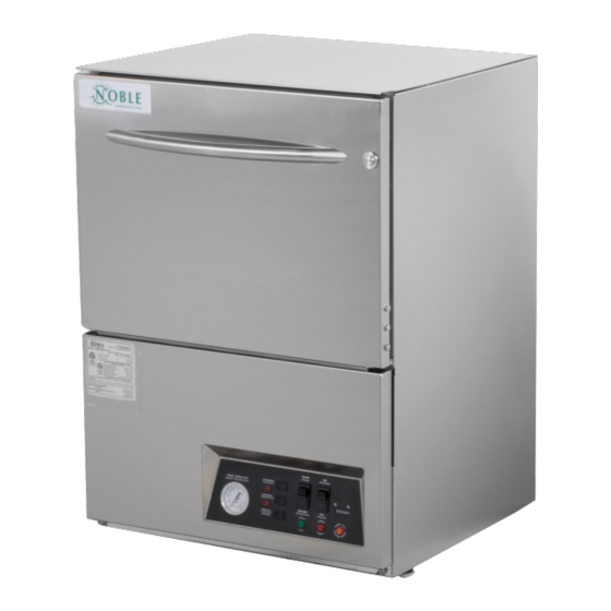
Summary of Contents for Noble UH30
- Page 1 NOBLE SERIES ELECTRICALLY HEATED UNDERCOUNTER DISHMACHINES INSTALLATION, OPERATION & SERVICE MANUAL FOR NOBLE MODEL(S): NOBLE UH30 NOBLE UL30 NOBLE UH30/UL30 Technical Manual • P/N 07610-004-25-09-C • Issued 06-05-15 • Revised 11-22-17...
- Page 3 REVISION HISTORY Revision Revision Date Made By Applicable ECNs Details Letter 06-04-15 Release to production 09-18-17 Changed HP from 3/4 to 1 11-22-17 Updated front page image...
-
Page 4: Phone Number
NOMENCLATURE NOBLE UH30 High temperature, hot water sanitizing, with a booster tank. Detergent & rinse aid chemical feeder pumps. NOBLE UL30 Low temperature, chemical sanitizing, no booster tank. Detergent, rinse aid & sanitizer chemical feeder pumps. Detergent & rinse aid chemical feeder pumps Model: Serial No.:... - Page 5 VACUUM SWITCH ASSEMBLY ......................53 VACUUM SWITCH ASSEMBLY INSTALLATION ................... 54 SCHEMATICS NOBLE UH30 208-230 VOLT, 60 HERTZ, SINGLE PHASE ..............55 NOBLE UH30 480 VOLT, 60 HERTZ, THREE PHASE ................56 NOBLE UL30 115 VOLT, 60 HERTZ, SINGLE PHASE ................57...
- Page 6 UH30 MACHINE DIMENSIONS SPECIFICATIONS WALL LEGEND: WALL Wall Clearance Wall Clearance GEND: A - Water Inlet - 1/2" Female Pipe Thread, [40mm] 4 [6mm] [40mm] 4 [6mm] 2 1/2" AFF (Connect to a true 1/2" ID Water Inlet - 1/2" Female Pipe Thread,...
- Page 7 UL30 MACHINE DIMENSIONS SPECIFICATIONS WALL LEGEND: WALL Wall Clearance END: Wall Clearance A - Water Inlet - 1/2" Female Pipe Thread, 16 [40mm] 4 [6mm] [40mm] 4 [6mm] ater Inlet - 1/2" Female Pipe Thread, 2 1/2" AFF (Connect to a true 1/2" ID 1/2"...
-
Page 8: Operating Parameters
OPERATING PARAMETERS SPECIFICATIONS Model Designation: NOBLE UH30 NOBLE UL30 Operating Capacity: Racks per Hour Dishes per Hour Glasses per Hour Tank Capacity (Gallons): Wash Tank Rinse Tank Electrical Loads (as applicable): Wash Motor HP Rinse Heater KW NOTE: Always refer to the machine data plate for specific electrical and water requirements. -
Page 9: Electrical Requirements
Work should only be performed PHASE by qualified electricians and authorized service agents. FREQ Note that all electrical wiring used in the NOBLE UH/UL30 series of machines must be rated, at a minimum, for 100 ◦ C (212 ◦ F). WASH MOTOR 6.6 A 6.6 A... -
Page 10: Installation
If such a situation occurs, DO NOT RETURN THE UNIT TO NOBLE. Instead, contact the carrier and ask them to send a representative to the site to inspect the damage. You should request that an inspection report be completed. - Page 11 HTS-11 outlet to the incoming water connection point using copper pipe (or order the 1/2” ID flexible hose kit offered by Noble). The water supply is to be capable of 20 PSI (plus or minus 5 PSI) “flow” pressure at the recommended temperature indicated on the data plate.
- Page 12 & sub floor material must be designed and/or selected with these higher temperatures in mind. Note: any damage to surrounding area that is caused by heat and or moisture to materials selected that are NOT recommended for higher temperatures will not be covered under warranty or by Noble Warewashing.
- Page 13 INSTRUCTIONS INSTALLATION THERMOSTATS: The thermostats on your NOBLE UH/UL30 unit have been set at the factory. They should only be adjusted by an authorized service agent. CHEMICAL FEEDER This equipment is not recommended for use with deionized water or other aggressive fluids.
- Page 14 INSTRUCTIONS INSTALLATION PRIMING CHEMICAL 1. Verify that the proper chemical tube stiffener inlet is in the proper container. 2. Use the prime switches located on the control panel at the bottom of the unit to FEEDER PUMPS prime each pump. The switches are clearly marked as to what chemical feeder (CONTINUED): pump they are assigned to.
- Page 15 INSTRUCTIONS INSTALLATION PROGRAMMING To access the programming mode, the machine must be ON and idle (between cycles). INSTRUCTIONS FOR CHEMICAL On the timer board, press and hold both the MOVE and ENTER buttons on the FEEDER PUMPS timer board simultaneously for two seconds. (INSTALLATION TECHNICIAN ONLY): The PROGRAM (PGM) light and light A will illuminate.
- Page 16 INSTRUCTIONS INSTALLATION PROGRAMMING NOBLE UH30 NOBLE UL30 INSTRUCTIONS Not Adjustable Rinse Aid FOR CHEMICAL Rinse Fill FEEDER PUMPS Detergent Sanitizer (INSTALLATION Rinse Aid Detergent TECHNICIAN ONLY): TIMER PROGRAMMING BOARD TIME IN SECONDS ACCEPT MOVE ENTER...
- Page 17 Water temperature is important in removing soil and sanitizing dishes. If the water cannot get hot enough, your results may not be satisfactory. This is why Noble recommends that if you have installed the machine in an area with hard water, that you also install some type of water treatment equipment to help remove the dissolved solids from the water before it gets to the dish machine.
- Page 18 (CONTINUED): and the rinse tank, depending on what model of dish machine you have installed. These temperatures may also be followed by temperatures that Noble recommends to ensure the highest performance from you dish machine. However, if the minimum requirements are not met, the chances are your dishes will not be clean or sanitized.
-
Page 19: Operating
The machine will run a partial cycle and fill to the bottom of the pan strainer. Open the door and verify that the water level is correct. NOTE: For the NOBLE UH30: Ensure the orange/white wires at the heater contactor are connected properly. They have been purposely disconnected at the factory to avoid damage to the heater element when there is no water in the booster heater. -
Page 20: Operating Instructions
OPERATING INSTRUCTIONS INSTALLATION DAILY MACHINE Refer to the section entitled “PREPARATION” at the top of this page and follow the instructions there. Afterwards, check that all of the chemical levels are correct and/or PREPARATION: that there is plenty of detergent available for the expected workload. WARM-UP CYCLES: For a typical daily start-up, it is recommended to run the machine through 3 cycles to ensure that all of the cold water is out of the system and to verify that the unit is... -
Page 21: Delime
NOTE: If this machine is equipped with a HTS-11, scale prevention and corrosion control device, and lime is becoming a frequent problem, the cartridge needs to be replaced. To order a replacement cartridge, call Noble immediately to have one shipped to you. -
Page 22: Preventative Maintenance
However, this does not mean that some items MAINTENANCE: will not wear out in time. Noble highly recommends that any maintenance and repairs not specifically discussed in this manual should be performed by QUAL- IFIED SERVICE PERSONNEL ONLY. Performing maintenance on your dish machine may void your warranty if it is still in effect. - Page 23 PREVENTATIVE MAINTENANCE MAINTENANCE PREVENTATIVE 1. Ensure that the water temperatures match those listed on the machine data plate. MAINTENANCE 2. Ensure that all strainers are in place before operating the machine. (CONTINUED): 3. Ensure that all wash and/or rinse arms are secure in the machine before operating.
-
Page 24: Troubleshooting
TROUBLESHOOTING COMMON PROBLEMS MAINTENANCE WARNING: Inspection, testing and repair of electrical equipment should be performed only by qualified service personnel. Certain procedures in this section require electrical tests or measurements while power is applied to the machine. EXERCISE EXTREME CAUTION AT ALL TIMES. If test points are not easily accessible, disconnect power, attach test equipment and reapply power to test. -
Page 25: Parts
TROUBLESHOOTING COMMON PROBLEMS MAINTENANCE WARNING: Inspection, testing and repair of electrical equipment should be performed only by qualified service personnel. Certain procedures in this section require electrical tests or measurements while power is applied to the machine. EXERCISE EXTREME CAUTION AT ALL TIMES. If test points are not easily accessible, disconnect power, attach test equipment and reapply power to test. -
Page 26: Control Panels
PRELIMINARY CHANGE DESIGN 4-26-07 PRELIMINARY CHANGED 6-32 TO 10-24 LOCKNUT & HEYCO CLAMP TO 5-14-07 NYLON NOBLE UH30 CONTROL PANEL PARTS ITEM DESCRIPTION PART NUMBER Heyco Open/Closed Busing .875 5975-003-35-21 Relay, Omron 05945-111-89-75 Screw, 6-32 X 3/8 05305-002-25-91 Control Panel Weldment... - Page 27 NOBLE UL30 CONTROL PANEL PARTS ITEM DESCRIPTION PART NUMBER W- Control Panel LT with Heater 05700-003-45-73 Timer, Universal Polytron 05945-003-33-09 Contactor, 115V, 30A 05945-109-05-69 Screw, 10-32 3/8” Long Phil Truss 05700-003-31-48 Locknut, 10 -24 S/S Hex w/ Nylon Ins. 05305-173-12-00 Heyco Open/Closed Busing .875...
- Page 28 NOBLE UH30 480V CONTROL PANEL PARTS ITEM DESCRIPTION PART NUMBER Electrical Panel Weldment 05700-003-37-46 Timer, Bracket Assembly 05700-003-36-05 Timer, Universal 05945-003-33-09 Fused Universal Timer (Alternate Construction) 05945-003-75-23 Fuse 05920-003-75-24 9 Wire Harness 05999-003-75-81 10 Wire Harness 05999-003-87-88 Relay 05945-002-47-41 Terminal Board...
-
Page 29: Kick Panel Weldment
KICK PANEL WELDMENT UH30 PARTS ITEM DESCRIPTION PART NUMBER Control Panel 09330-003-31-66 Decal, Control Panel 09905-003-31-65 Locknut, 1/4” -20 S/S Hex w/ Nylon Insert 05310-374-01-00 Thermometer, 48” Rinse 06685-111-68-48 Light, Amber 05945-111-44-44 Thermometer, 96” Wash 06685-111-68-49 Light, Red 05945-111-44-45 Window Plug... -
Page 30: Terminal Block Box Assembly
TERMINAL BLOCK BOX ASSEMBLY PARTS ITEM DESCRIPTION PART NUMBER Decal. Power Connections 09905-011-47-35 Terminal Block Box 05700-003-27-69 Terminal Box Cover (not shown) 05700-003-27-70 Decal, Copper Conductors 09905-001-62-72 Screw, 1--32 X 1/2” 05305-011-39-36 Ground Lug 05940-200-76-00 Screw, 1--32 X 1/2” 05305-011-39-36 2 (3 per 480V) Terminal Block 05940-500-02-19... - Page 31 COMPLETE UH30 PERIPUMP TRACK ASSEMBLY PARTS ITEM DESCRIPTION PART NUMBER Screw, 10-32 X 5/8” PH Truss HD 05305-003-02-12 Track, Peripump HT 05700-003-33-44 A-Track Mount HT 05700-003-33-52 Locknut, 10-32 With Nylon Insert 05310-373-02-00...
- Page 32 COMPLETE UL30 PERIPUMP TRACK ASSEMBLY PARTS ITEM DESCRIPTION PART NUMBER Complete Noble UL30 Peripump Track Assembly 05700-003-33-31 Bracket, Track Mounting 05700-003-33-30 Track, Peripump 05700-003-33-29 Screw, 10-32 X 5/8” Truss Head 05305-003-02-12...
- Page 33 UH30 CHEMICAL FEEDER PUMP ASSEMBLY PARTS ITEM DESCRIPTION PART NUMBER A-Peri Pump, 14 RPM 05700-002-72-82 A-Peri Pump, 36 PRM 240V/Red Tygoprene 05700-003-78-74 Strap, Nylon Loop 04320-002-71-22 CW 750 PE UV Black 8924 12” 05700-003-33-63 W Peripump Slide 05700-003-33-48 A-Stop Bracket 05700-003-36-24 Screw, 10-32 X 3/8”...
- Page 34 UL30 CHEMICAL FEEDER PUMP ASSEMBLY PARTS ITEM DESCRIPTION PART NUMBER W-Peri Pump Channel 05700-003-53-25 Swtich, Vaccum 06685-003-36-13 F-Pressure Swtich Bracket 05700-003-53-03 Lockenut, 10-24 S/S Hex W/ Nylon Inserts 05310-373-01-00 Motor, 105-3036-2 36 RPM 04320-111-35-14 Motor, 14 RPM Peri Pump 04320-111-35-13 A-Kit, Peri Pump Assy W/ White Roller 04320-002-83-90 Tube Stiffener...
-
Page 35: Chemical Feeder Pump Components
CHEMICAL FEEDER PUMP COMPONENTS PARTS ITEM DESCRIPTION PART NUMBER Rear Housing 04320-111-37-09 Screw, 8-32 X 3/8” Phillips Pan Head 05305-011-37-07 Screw, 6-32 X 32 X 3/4” Phillips Pan Head 05305-011-37-05 Front Housing 04320-111-37-08 Roller, Black 04320-111-65-27 Roller, White 04320-002-82-28 Tygoprene Tube 05700-03-22-89 Screw, 8-32 X 1/2”... -
Page 36: Plumbing Assemblies
UH30 PLUMBING ASSEMBLIES PARTS A-Injector, Incoming Assembly... - Page 37 1/2 “ Plumbing Section 05700-003-32-17 A-Plumbing, Inlet Booter 05700-003-33-97 A-Plumbing, Inlet Vavle-Booster 05700-003-33-98 A-Plumbing, Inlet Hook-Up 05700-003-33-99 A-Injector, Incoming Assembly 05700-003-22-01 Assy, Noble UH30 Vaccum Break 05700-003-32-15 Vac BRKR 1/2 Brass Bon.EDP-0336402 04820-003-06-13 Nipple-1/2 Close Brass 04730-207-15-00 Clamp, Pipe 05700-000-35-05 Clamp, Pipe 05700-011-38-62...
-
Page 38: Vacuum Breaker Repair Parts Kit
VACUUM BREAKER REPAIR PARTS KIT PARTS RINSE SOLENOID VALVE & VACUUM BREAKER REPAIR PARTS KIT/WATER HAMMER KIT OPTION Complete Vacuum Breaker Assembly Solenoid Valve Assembly... - Page 39 VACUUM BREAKER REPAIR PARTS KIT PARTS RINSE SOLENOID VALVE & VACUUM BREAKER REPAIR PARTS KIT/WATER HAMMER KIT OPTION ITEM DESCRIPTION PART NUMBER Complete 110 Volt Solenoid Valve Assembly 1/2” Assembly 04810-100-12-18 Coil & Housing Only 1/2” 06401-003-07-43 Complete 220 Volt Solenoid Valve Assembly 1/2” Assembly 04810-003-07-43 Coil &...
-
Page 40: Wash Manifold Assembly
NOBLE UL30 WASH MANIFOLD ASSEMBLY PARTS WASH MOTOR/DRAIN PLUMBING/NOBLE UL30 WASH MANIFOLD ASSEMBLY Noble UL30 Noble UL30 NOBLE UL30 115V & NOBLE UH30 480V: NOBLE UH30 230V:... - Page 41 NOBLE UL30 WASH MANIFOLD ASSEMBLY PARTS WASH MOTOR/DRAIN PLUMBING/NOBLE UL30 WASH MANIFOLD ASSEMBLY ITEM DESCRIPTION PART NUMBER Hub, Discharge Machine (Noble UH30 Shown) 05700-021-37-90 Lower, Wash Manifold (Noble UL30) 05700-021-52-80 Gasket, Manifold 05330-200-23-00 Nut, Jam 1-1/2” -12 NPT 05700-000-86-23 Hose Clamp, 1-5/16”-2 1/4” #28 04730-719-01-37 Hose, 1-1/4”...
-
Page 42: Motor & Pump Assembly
MOTOR & PUMP ASSEMBLY PARTS... - Page 43 MOTOR & PUMP ASSEMBLY PARTS ITEM DESCRIPTION PART NUMBER Complete Pump & Motor Assembly, 60 HZ Bracket 05700-003-31-57 Complete Pump & Motor Assembly, 480V, 60 HZ Bracket 05700-003-52-80 Complete Pump & Motor Assembly, 60 HZ No Bracket 06105-002-72-75 Complete Pump & Motor Assembly, 480V, 60 HZ No Bracket 06105-003-52-78 Pump Only Assembly, 60 HZ 05700-002-79-50...
-
Page 44: Rinse Arm & Wash Arm Assemblies
RINSE ARM & WASH ARM ASSEMBLIES PARTS Rinse Arm Wash Arm ITEM DESCRIPTION PART NUMBER Rinse Arm Assembly (Noble UH30 units ONLY) 05700-031-39-21 Plug, Rinse Arm 04730-609-04-00 Rinse Arm 05700-031-38-30 Washer, Rinse Arm 05330-011-42-10 O-Ring (not shown) 05330-002-60-69 Ring, Retaining 05340-112-01-11 Bushing. -
Page 45: Uh30 Thermostat & Rinse Tank Assembly
UH30 THERMOSTAT & RINSE TANK ASSEMBLY PARTS ITEM DESCRIPTION PART NUMBER Rinse Tank Weldment 05700-003-31-95 Fittin, 1/4” Imperial Brass 05310-924-02-05 Heater: 208-230 Volt 04540-111-43-21 Heater: 480 Volt 04540-002-29-82 Lock Washer, 5/16” Split 05311-275-01-00 Nut, Hex 5/16”- 18 S/S Hex 05310-275-01-00... - Page 46 NOBLE UL30 OPTIONAL PARTS THERMOSTAT & HEATER COMPONENTS ITEM DESCRIPTION PART NUMBER Wash Thermostat 05930-003-13-65 Heater, Fire Bar 04540-003-46-27 Insulation Paper 1/8” 04540-003-46-30 Heater Cover Plate 05700-003-46-37 High Limit Thermostat 06685-003-46-77...
-
Page 47: Door Assembly
PARTS NOBLE UH/UL30 DOOR ASSEMBLY... - Page 48 NOBLE UH/UL30 DOOR ASSEMBLY PARTS ITEM DESCRIPTION PART NUMBER Outer Door Weldment 05700-003-33-37 Inner Door Weldment 05700-003-33-21 Door Handle 05700-003-26-62 Bolt, 1/4”-20 X 3/8” Long 05305-274-20-00 Channel, Right Seal 05700-003-33-19 Channel, Left Deal 05700-003-33-20 Channel, Top Seal 05700-003-33-22 Screw, 10-32 X 1/2” Pan Phillips Head...
-
Page 49: Clyde Switch Arm
CLYDE SWITCH ARM PARTS ITEM DESCRIPTION PART NUMBER Clyde Switch Arm Assembly 05700-003-52-14 F-Plate, Switch Cover RT 05700-003-52-10 Screw, 6-32 X 5/8” 05305-011-39-85 Lock Nut 6-32 Hex w/ Nylon Insert 05310-373-03-00 Cycle Switch Weldment 05700-003-36-81 Term, 190030013 .187 Pink Reel 05940-111-45-18 Wire Nut, Blue Metal 30-172 Ideal 05945-111-01-00... -
Page 50: Miscellaneous Door Components
MISCELLANEOUS DOOR COMPONENTS PARTS... - Page 51 MISCELLANEOUS DOOR COMPONENTS PARTS ITEM DESCRIPTION PART NUMBER Switch Mounting Plate Assembly 05700-003-33-54 Door Spring 05700-003-32-85 Hinge Stop Assembly: Right 05700-003-32-61 Hinge Stop Assembly: Left (not shown) 05700-003-32-60 Hinge Stop Assembly: Right 05700-003-32-63 Hinge Stop Assembly: Left (not shown) 05700-003-32-61 Cover, Left Hinge Weldment 05700-002-18-41 Cover, Right Hinge Weldment...
-
Page 52: Frame And Panel Components
FRAME AND PANEL COMPONENTS PARTS... - Page 53 FRAME AND PANEL COMPONENTS PARTS ITEM DESCRIPTION PART NUMBER Top Shroud Weldment 05700-003-37-06 Left Shroud Weldment 05700-003-37-04 Right Shroud Weldment 05700-003-37-05 Left Frame Weldment 05700-003-31-91 Swivel Feet 05340-108-02-00 Right Frame Weldment 05700-003-31-90 Hardware: Nut, 1/4”-20 Serrated Hex 05310-959-03-00 Nut, 5/16”-18 Cad Spine 05310-959-03-00 Optional Bottom Panel 05700-003-32-92...
-
Page 54: Miscellaneous Parts
MISCELLANEOUS PARTS PARTS ITEM DESCRIPTION PART NUMBER Components secured with: Locknut, 1/4”-20 S/S Hex with Nylon Insert 05310-374-01-00 Rail, Left Rack 05700-031-37-88 Rail, Right Rack 05700-031-37-88 Splash Shield 05700-003-33-51 Strainer Spacer 05700-001-35-83 Attaches with: Nut, Nylon Wing, 1/4”-20 05310-994-01-00 Strainer Weldment 05700-003-32-81... -
Page 55: Stands & Components
STANDS & COMPONENTS PARTS INSTALLATION To install the stand, first remove the adjustable feet from the machine. Place machine on table and use the square mounting holes to line up the machine. Re-insert the INSTRUCTIONS: adjustable feet through bottom of table top and tighten to lock machine to table. ITEM DESCRIPTION PART NUMBER... -
Page 56: Hts-11 Scale Prevention & Corrosion Control Device
HTS-11 SCALE PREVENTION PARTS & CORROSION CONTROL DEVICE INSTALLATION Must be installed vertically. The provided bracket is to be secured to the wall. Observe proper inlet/outlet water directions. Flow directions are molded into the INSTRUCTIONS: top of the head. Line pressure should be released prior to changing cartridges. De- liming of equipment prior to installation is recommended but no required. - Page 57 GO BOX KIT PARTS A GO Box is a kit of the most needed parts for a particular model or model family to successfully effect a repair in the first call 90% or more of the time. ITEM DESCRIPTION PART NUMBER Rinse Thermostat 05930-003-06-48 Contactor/Heater...
-
Page 58: Vacuum Switch Assembly
VACUUM SWITCH ASSEMBLY PARTS ITEM DESCRIPTION PART NUMBER Complete Assembly 05700-003-55-98 Box, Vacuum Switch 05700-003-55-96 Switch, Vacuum 05700-003-36-13 Wye, 1/4” Barbed PVDF 04730-003-36-14 Tubing, Clear 5/16 ID 04710-003-53-26 A-Tube, Red 1/4 OD X 100 Long 05700-003-03-45 A-Tube, White 1/4 OD X 100 Long 05700-003-03-45 Fitting, Liquidtite .231 X .394 Heyco 05700-003-20-67... -
Page 59: Vacuum Switch Assembly Installation
VACUUM SWITCH ASSEMBLY INSTALLATION PARTS Remove locknut on plumbing support brackets and mount switch box over existing stud. Re-install bracket and route red and white tubes behind blue hose as shown. Route gray cable down back and under tub along inlet plumbing, remove wires from existing pressure switches and connect gray cable per note below. - Page 60 NOBLE UH30 SCHEMATICS 208-230 VOLT, 60 HERTZ, SINGLE PHASE...
-
Page 61: Noble Uh30 480 Volt, 60 Hertz, Three Phase
SCHEMATICS NOBLE UH30 480 VOLT, 60 HERTZ, THREE PHASE... - Page 62 NOBLE UL30 SCHEMATICS 115 VOLT, 60 HERTZ, SINGLE PHASE...
- Page 64 Noble Warewashing • Lancaster, Pennsylvania www.nobleproducts.biz NOBLE UH30/UL30 Technical Manual • P/N 07610-004-25-09 • Issued 06-05-15 • Revised N/A...
Need help?
Do you have a question about the UH30 and is the answer not in the manual?
Questions and answers