
Subscribe to Our Youtube Channel
Related Manuals for Noble UH30-E


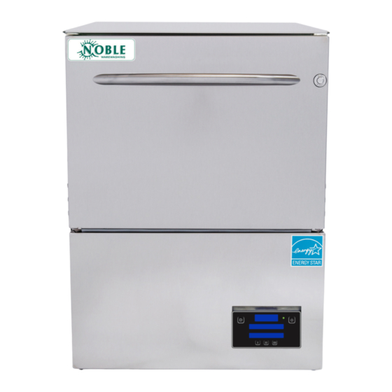
Summary of Contents for Noble UH30-E
- Page 1 NOBLE UNDERCOUNTER DISHMACHINES INSTALLATION, OPERATION, AND SERVICE MANUAL NOBLE UH30-E UH30-E Manual • 07610-004-45-09-D...
- Page 2 Replaced 7/8" discharge hose with 5/8" discharge hose (05700-004-46-28) on pg. 31. Updated view of inlet plumbing on pg. 34 to show angle of elbow and adapter. Updated schematic to revision E. Added the UH30-E-SEER to the manual. 8537 Updated the Door Assembly pages.
- Page 3 NOMENCLATURE UH30-E Undercounter dishmachine; high-temperature, hot-water sanitizing, with a booster tank and detergent and rinse-aid chemical feeder pumps. UH30-E-SEER Undercounter dishmachine; high-temperature, hot-water sanitizing, with a booster tank and detergent and rinse-aid chemical feeder pumps. Equipped with Steam Elimination and Energy Recovery System (SEER).
-
Page 4: Table Of Contents
GUIDES Symbols ............................1 Abbreviations & Acronyms ....................... 1 SPECIFICATIONS UH30-E Dimensions ......................... 2 UH30-E-SEER Dimensions ......................3 UH30-E Operating Parameters ......................4 UH30-E-SEER Operating Parameters ..................... 5 Electrical Requirements ........................6 INSTRUCTIONS Installation Instructions ........................7 Inspection......................... 7 Unpacking ........................7 Plumbing .......................... - Page 5 Terminal Block Box, 208/230 V ...................... 29 Terminal Block Box, 460 V ......................30 Control Kick Panel .......................... 31 UH30-E Electrical Panel, 208/230 V ....................32 UH30-E Electrical Panel, 460 V ..................... 33 UH30-E-SEER Electrical Panel, 208/230 V ................... 34 UH30-E-SEER Electrical Panel, 460 V ..................
-
Page 6: Symbols
GUIDES SYMBOLS - Risk of Injury to Personnel WARNING - Risk of Damage to Equipment CAUTION - Risk of Electrical Shock - Caustic Chemicals - Reference Data Plate - Lockout Electrical Power - Important Note NOTICE - Instructions Hyperlink ABBREVIATIONS &... -
Page 7: Specifications
UH30-E DIMENSIONS SPECIFICATIONS LEGEND A - Electrical Connection C - Drain Connection LEGEND (1" ID, 1 3/8" OD) A - Electrical Connection C - Drain Connection B - Water Inlet (with 6' Hose) (Connect to MIN 1 1/2" Drain with Air-gap) (1"... -
Page 8: Uh30-E-Seer Dimensions
UH30-E-SEER DIMENSIONS SPECIFICATIONS LEGEND LEGEND A - Electrical Connection C - Drain Connection A - Electrical Connection C - Drain Connection (1" ID, 1 3/8" OD) (1" ID, 1 3/8" OD) B - Water Inlet (with 6' Hose) (Connect to MIN 1 1/2" Drain with Air-gap) B - Water Inlet (with 6' Hose) (Connect to MIN 1 1/2"... -
Page 9: Uh30-E Operating Parameters
UH30-E OPERATING PARAMETERS SPECIFICATIONS UH30-E Operating Capacity: Racks per Hour Dishes per Hour Glasses per Hour Tank Capacity (Gallons): Wash Tank Rinse Tank 1.66 NOTICE Always refer to the machine data plate for specific electrical and water requirements. The material provided on this page is for reference only and is subject to change without notice. -
Page 10: Uh30-E-Seer Operating Parameters
UH30-E-SEER OPERATING PARAME- SPECIFICATIONS UH30-E-SEER Operating Capacity: Racks per Hour Dishes per Hour Glasses per Hour Tank Capacity (Gallons): Wash Tank Rinse Tank 1.66 NOTICE Always refer to the machine data plate for specific electrical and water requirements. The material provided on this page is for reference only and is subject to change without notice. -
Page 11: Electrical Requirements
4 kW (460 V) Available Rinse Tank Heaters: • 4.1 kW (208 V)/5.45 kW (230 V) • 5.45 kW (460 V) *The UH30-E is designed so the heaters never run simultaneously. Total Load is based on the higher of the two loads. 07610-004-45-09-D... -
Page 12: Instructions
See the UH30-E Dimensions or UH30-E-SEER Dimensions page (depending on your model) and reference item "B" for water inlet connection location. -
Page 13: Pressure Regulator
REGULATOR option (see the Plumbing Options page). The PRV comes standard on the UH30-E- Take care not to confuse SEER. Do not confuse static pressure with flow pressure. Static pressure is the line static pressure with pressure in a “no flow”... -
Page 14: Electrical Power Connections
INSTRUCTIONS INSTALLATION ELECTRICAL POWER Electrical and grounding conductors must comply with the applicable portions of the National Electric Code ANSI/NFPA 70 (latest edition) and/or other electrical codes. CONNECTIONS The data plate is located on the left-front of the dishmachine. Refer to the data plate for machine operating requirements, machine voltage, total amperage, and serial number. -
Page 15: Voltage Check
INSTRUCTIONS INSTALLATION VOLTAGE CHECK Apply power to machine. Check the incoming power at the terminal block and ensure it corresponds with the voltage listed on the data plate. If not, contact a qualified service agency to examine the problem. Do not run the machine if voltage is too high or too low. -
Page 16: Preparing Chemical Feeder Pumps
INSTRUCTIONS INSTALLATION PREPARING This machine is supplied with detergent and rinse-aid chemical feeder pumps. CHEMICAL Locate the open ends of the chemical tubes with the tube stiffeners and place each FEEDER PUMPS one in the appropriate container. A. Red Tubing = Detergent B. -
Page 17: Programming Chemical Feeder Pumps
INSTRUCTIONS INSTALLATION PROGRAMMING To access the programming mode, the machine must be ON and "READY" (between cycles). CHEMICAL On the timer board, press and hold both the MOVE and ENTER buttons simultaneously FEEDER PUMPS for two seconds. The PROGRAM (PGM) light and light A will illuminate. Once in the programming mode, the MOVE button is used to scroll between NOTICE the programming categories and the ENTER button is used to select the... -
Page 18: Operating Instructions
OPERATING INSTRUCTIONS OPERATION PREPARATION Before operating the machine, verify the following: 1. Strainers are in place and clean. 2. Wash and rinse arms are screwed securely into place and end-caps are tight. 3. Wash and rinse arms rotate freely. 4. Chemical levels are correct. POWER UP To energize the machine, turn on the power at the service breaker. -
Page 19: Ware Preparation
OPERATING INSTRUCTIONS OPERATION WARE Proper ware preparation helps ensure good results and fewer re-washes. If not done properly, ware might not come out clean and the efficiency of the dishmachine will PREPARATION be reduced. Scraps should always be removed from ware before being loaded into a rack. - Page 20 OPERATING INSTRUCTIONS OPERATION WASHING A RACK 6. Press the “Start” button and the machine will begin the wash cycle. OF WARE 1 5 5 F Temperature shown is the minimum required W A S H I N G temperature. C Y C L E 1 7.
-
Page 21: Operational Inspection
OPERATING INSTRUCTIONS OPERATION OPERATIONAL Based on use, the strainers might become clogged with soil and debris as the workday progresses. Operators should regularly inspect the strainers to ensure they INSPECTION have not become clogged. Clogged strainers will reduce the washing capability of the machine. - Page 22 OPERATING INSTRUCTIONS OPERATION SHUTDOWN & 6. Replace end-caps and use a screwdriver to ensure they are tight. CLEANING Use a screwdriver to ensure end-caps are tight. 7. Ensure the float is free of debris. 8. Spray or wipe out interior of machine. 9.
-
Page 23: Deliming
DELIMING OPERATION DELIMING In order to maintain the machine at its optimum performance level, lime and corrosion deposits must be removed. The frequency for deliming will be based on water conditions. A deliming solution is available from your chemical supplier. Read and follow all instructions on the label. -
Page 24: Detergent Control
DETERGENT CONTROL OPERATION DETERGENT Detergent usage and water hardness are two factors that contribute greatly to how efficiently this machine operates. Using detergent in the proper amount can become CONTROL a source of substantial savings. A qualified water treatment specialist can determine what is needed for maximum efficiency from the detergent. -
Page 25: Maintenance
PREVENTATIVE MAINTENANCE MAINTENANCE PREVENTATIVE The manufacturer of this machine highly recommends that any maintenance and repairs not specifically discussed in this manual only be performed by qualified service MAINTENANCE personnel. Performing maintenance on the machine may void a warranty. By following the operating and cleaning instructions in this manual, users should get the most efficient results from the machine. - Page 26 PREVENTATIVE MAINTENANCE MAINTENANCE PREVENTATIVE 5. Do not overfill racks. MAINTENANCE 6. Ensure that glasses are placed upside-down in the rack. 7. Ensure that all chemicals being injected into machine have been verified at the correct concentrations. 8. Clean the machine at the end of every workday (see "Shutdown and Cleaning" section).
-
Page 27: Troubleshooting
PROGRAMMING TROUBLESHOOTING PROGRAMMING To access programming, the machine should be on and not in cycle. The programming buttons (Up-arrow, Down-arrow, and Select) are hidden on the display and are shown below as red outlines. There is a full-size display template at the end of the manual to help locate the programming buttons. - Page 28 PROGRAMMING TROUBLESHOOTING PROGRAMMING To access programming, the machine should be on and not in cycle. The programming buttons (Up-arrow, Down-arrow, and Select) are hidden on the display and are shown below outlined with red dots. There is a full-size display template at the end of the manual to help locate the programming buttons.
-
Page 29: Fault Codes
FAULT CODES TROUBLESHOOTING DISPLAY SHOWS POSSIBLE CAUSES REMEDY 1. Verify incoming water pressure is 10 ± 2 PSI. 1. Low or no water pressure. 2. Verify that fill relay is supplying voltage to fill solenoid. Replace faulty component. 2. Faulty inlet valve or fill relay. 3. - Page 30 FAULT CODES TROUBLESHOOTING DISPLAY SHOWS POSSIBLE CAUSES REMEDY 1. Verify incoming water pressure is 10 ± 2 PSI. 1. Low or no water pressure. 2. Verify that fill relay is supplying voltage to fill solenoid. 2. Faulty inlet valve or fill relay. Replace faulty component.
- Page 31 FAULT CODES TROUBLESHOOTING DISPLAY SHOWS POSSIBLE CAUSES REMEDY F12 - Not Used 1. Fully disconnect 6-pin cable at each end, and reconnect 1. Loose connection in 6-pin cable between each end until a click is heard. display board and I/O module. 2.
-
Page 32: Troubleshooting
TROUBLESHOOTING TROUBLESHOOTING WARNING! Inspection, testing, and repair of electrical equipment should only be performed by qualified service personnel. Certain procedures in this section require electrical tests or measurements while power is applied to the machine. Exercise extreme caution at all times. If test points are not easily accessible, disconnect WARNING power, attach test equipment, and reapply power to test. - Page 33 TROUBLESHOOTING TROUBLESHOOTING WARNING! Inspection, testing, and repair of electrical equipment should only be performed by qualified service personnel. Certain procedures in this section require electrical tests or measurements while power is applied to the machine. Exercise extreme caution at all times. If test points are not easily accessible, disconnect WARNING power, attach test equipment, and reapply power to test.
-
Page 34: Parts
TERMINAL BLOCK BOX, 208/230 V PARTS ITEM DESCRIPTION PART NUMBER Power Connection Decal 09905-011-47-35 Terminal Block Box 05700-004-36-47 Terminal Box Cover (not shown) 05700-003-27-70 Strain Relief 05975-003-37-56 Terminal Block Track 05700-000-43-60 Terminal Block 05940-500-02-19 Locknut, 10-24 Hex with Nylon Insert 05310-373-01-00 Decal, L1, N 09905-011-62-72... -
Page 35: Terminal Block Box, 460 V
TERMINAL BLOCK BOX, 460 V PARTS ITEM DESCRIPTION PART NUMBER Power Connection Decal 09905-011-47-35 Terminal Block Box 05700-004-44-79 Terminal Box Cover (not shown) 05700-004-44-80 Strain Relief 05975-210-03-00 Terminal Block Track 05700-004-44-72 Terminal Block 05940-500-02-19 Locknut, 8-32 Low Profile 05310-004-23-83 Decal, L1, L2, L3 09905-101-12-66 Ground Lug 05940-200-76-00... -
Page 36: Control Kick Panel
CONTROL KICK PANEL PARTS ITEM DESCRIPTION PART NUMBER Complete Control Kick Panel Assembly 05700-004-41-87 Control Kick Panel 05700-004-41-86 Locknut, 6-32 Hex with Nylon Insert 05310-373-03-00 P-clamp, 1/4" ID 05975-002-61-42 Bushing, Snap 05975-210-09-00 Locknut, 10-24 Hex with Nylon Insert 05310-373-01-00 Cover, Display 05700-004-46-05 Nut, Thumb 6-32 Nylon 05310-002-83-12... -
Page 37: Uh30-E Electrical Panel, 208/230 V
UH30-E ELECTRICAL PANEL, 208/230 V PARTS ITEM DESCRIPTION PART NUMBER Complete UH30-E Electrical Panel Assembly, 208/230 V 05700-004-42-07 Electrical Panel 05700-004-40-63 Contactor, 208/230 V 05945-002-74-20 Screw, 10-32 x 5/8" 05305-003-02-12 Screw, 10-32 x 1” 05305-002-19-42 PCB, Electronic Control 05945-004-36-34 Terminal Board... -
Page 38: Uh30-E Electrical Panel, 460 V
UH30-E ELECTRICAL PANEL, 460 V PARTS ITEM DESCRIPTION PART NUMBER Complete UH30-E Electrical Panel Assembly, 460 V 05700-004-44-50 Electrical Panel 05700-004-40-63 Contactor, 460 V 05945-111-60-07 End-cap, Contactor 05940-111-60-30 Dinrail, 7 3/4" 05700-002-79-13 Screw, 10-32 x 5/8" 05305-003-02-12 Motor Overload, 1.35 - 2 A 05945-111-60-08 Screw, 10-32 x 1”... -
Page 39: Uh30-E-Seer Electrical Panel, 208/230 V
UH30-E-SEER ELECTRICAL PANEL, 208/230 V PARTS ITEM DESCRIPTION PART NUMBER Complete UH30-E-SEER Electrical Panel Assembly, 05700-004-51-91 208/230 V Electrical Panel 05700-004-40-63 PCB, Electronic Control 05945-004-36-34 Contactor, 208/230 V 05945-002-74-20 Terminal Board 05940-002-78-97 Terminal Board 05940-004-21-34 Relay 05945-111-89-75 Fastener 05340-111-58-10 Nut, Plated 05340-118-04-00 Screw, 10-32 x 1”... -
Page 40: Uh30-E-Seer Electrical Panel, 460 V
UH30-E-SEER ELECTRICAL PANEL, 460 V PARTS ITEM DESCRIPTION PART NUMBER Complete UH30-E-SEER Electrical Panel Assembly, 460 V 05700-004-51-92 Electrical Panel 05700-004-40-63 PCB, Electronic Control 05945-004-36-34 Terminal Board 05940-002-78-97 Terminal Board 05940-004-21-34 Fastener 05340-111-58-10 Nut, Plated 05340-118-04-00 Screw, 10-32 x 1”... -
Page 41: Chemical Feeder Pumps
CHEMICAL FEEDER PUMPS PARTS Complete Peri-pump Panel Assembly, 208/230 V 05700-004-42-08 Complete Peri-pump Panel Assembly, 460 V 05700-004-44-45 07610-004-45-09-D... - Page 42 CHEMICAL FEEDER PUMPS PARTS ITEM DESCRIPTION PART NUMBER Stiffener, Chemical Tube 05700-002-66-49 Chemical Port Assembly 05700-004-30-86 Tubing, Red, 1/4" x 120" 05700-011-37-15 Tubing, Red, 1/4" x 80" 05700-011-37-14 Tubing, Clear, 1/8" x 120" 05700-002-76-14 Tubing, Clear, 1/8" x 48" 05700-002-76-15 Complete Peri-pump Assembly, 36 RPM, 208/230 V 05700-003-78-74 Motor Only, Peri-pump, 36 RPM, 208/230 V...
-
Page 43: Door
DOOR PARTS Complete Door Assembly 05700-004-36-53 07610-004-45-09-D... - Page 44 DOOR PARTS ITEM DESCRIPTION PART NUMBER Outer Door Weldment 05700-004-52-86 Screw, 10-32 x 1/4" 05305-173-01-00 Bolt, 1/4-20 x 3/8" Hex 05305-274-20-00 Washer, 1/4-20 ID 05311-174-01-00 Gasket, Door 20" 05330-003-58-35 Gasket, Door 17 1/8" 05330-003-58-36 Fastener, 10-32 05340-111-58-10 Door Handle 05700-003-26-62 Stop, Door Hinge 05700-003-32-55 Hinge, Left...
-
Page 45: Miscellaneous Door Components
MISCELLANEOUS DOOR COMPONENTS PARTS Parts are not shown to scale in relation to each other. ITEM DESCRIPTION PART NUMBER Switch Mounting Plate Assembly 05700-003-33-54 Door Spring 05700-003-32-85 Cover, Left Hinge Weldment 05700-004-36-80 Cover, Right Hinge Weldment 05700-004-36-81 Hinges secured with Locknut, 1/4-20 Hex with Nylon Insert 05310-374-01-00 O-ring 05330-003-32-34... -
Page 46: Uh30-E-Seer Door Interlock
UH30-E-SEER DOOR INTERLOCK PARTS Complete Door Interlock Assembly, 208/230 V 05700-004-47-47 Complete Door Interlock Assembly, 115 V (for 460 V Machine) 05700-004-52-89 ITEM DESCRIPTION PART NUMBER Solenoid, Door Interlock, 208/230 V 05999-004-47-49 Solenoid, Door Interlock, 115 V (for 460 V Machine) -
Page 47: Wash & Motor
WASH & MOTOR PARTS 07610-004-45-09-D... - Page 48 WASH & MOTOR PARTS ITEM DESCRIPTION PART NUMBER Wash Arm Assembly 05700-021-39-23 Motor Support 05700-004-40-61 Wash Halo 05700-004-42-21 Pipe Clamp 05700-000-35-06 Wash Arm End-cap 05700-003-31-59 Screw, 1/4-20 x 1/2" 05307-011-36-96 Locknut, 1/4-20 Hex with Nylon Insert 05310-374-01-00 Manifold Gasket 05330-002-34-77 Wash Hub 05700-004-43-04 Pump and Motor, 208/230 V...
-
Page 49: Rinse Manifold
RINSE MANIFOLD PARTS Rinse Arm Bearing Kit 06401-004-57-50 ITEM DESCRIPTION PART NUMBER Complete Rinse Manifold Assembly 05700-004-40-58 Pipe Clamp 05700-000-35-06 Rinse Arm End-cap 04730-111-60-41 Complete Rinse Arm Assembly 05700-004-39-39 Rinse Arm 05700-004-38-75 Bearing Assembly, Rinse Arm 05700-004-54-71 O-ring (included in item #5) 05330-002-60-69 Retaining Ring 05340-112-01-11... -
Page 50: Plumbing Options
PLUMBING OPTIONS PARTS SHOCK ABSORBER (WATER ARRESTOR) OPTION Water Arrestor, 1/2” 06685-100-05-00 NOTICE UH30-E-SEER has a water arrestor as standard equipment. See the SEER System page. Tee, 1/2” x 1/2” x 1/2” 04730-211-27-00 Nipple, 1/2” NPT, Brass 04730-207-15-00 Water Arrestor Repair Kit (Plunger &... -
Page 51: Uh30-E Plumbing
UH30-E PLUMBING PARTS Complete Inlet Plumbing Assembly, 208/230 V 05700-004-09-03 Complete Inlet Plumbing Assembly, 115 V (for 460 V Machine) 05700-004-44-40 *Item not included in part number of complete plumbing assembly and must be ordered separately. 07610-004-45-09-D... - Page 52 UH30-E PLUMBING PARTS ITEM DESCRIPTION PART NUMBER Valve, 1/2", 208/230 V 04810-003-71-56 04810-003-71-55 Valve, 1/2", 115 V (for 460 V Machine) Union, 1/2" x 1/2" Brass 04730-003-62-44 Nipple, 1/2" Close Brass 04730-207-15-00 Nipple, 1/2" x 4" NPT Brass 04730-207-04-00 Adapter, 1/2" Fitting, Male 04730-011-59-53 Elbow, 1/2"...
-
Page 53: Uh30-E-Seer Plumbing
UH30-E-SEER PLUMBING PARTS Complete SEER Plumbing Assembly, 208/230 V 05700-004-53-98 Complete SEER System Assembly, 460 V 05700-004-51-94 For water connection point, see NOTICE next page, item B on the UH30-E-SEER Dimensions page, and item #27 on the SEER System page. - Page 54 UH30-E-SEER PLUMBING PARTS Complete SEER PRV Plumbing Assembly 05700-004-56-92 See Item B on Also see UH30-E-SEER SEER Dimensions page. System page. ITEM DESCRIPTION PART NUMBER Plumbing Inlet, Offset 05700-004-56-93 PRV, 1/2" 04820-004-09-37 Garden Hose Connector 04730-004-24-76 07610-004-45-09-D...
-
Page 55: Rinse Plumbing
RINSE PLUMBING PARTS Complete Rinse Plumbing Assembly 05700-004-43-02 07610-004-45-09-D... - Page 56 RINSE PLUMBING PARTS ITEM DESCRIPTION PART NUMBER Vacuum Breaker, 1/2" Brass 04820-003-06-13 Nipple, 1/2" Brass, 2" Long 04730-207-19-00 Elbow, 90-Degree, 1/2" Street Brass 04730-206-08-00 Tee, 1/2" x 1/2" x 1/4" 04730-002-22-56 Union, 1/2" x 1/2" Brass 04730-003-62-44 Complete Rinse Injector Assembly 05700-004-43-86 Rinse Injector 09515-004-22-73...
-
Page 57: Rinse Tank
RINSE TANK PARTS Front of Rinse Tank Back of Rinse Tank 07610-004-45-09-D... - Page 58 RINSE TANK PARTS ITEM DESCRIPTION PART NUMBER Rinse Tank, 208/230 V 05700-004-41-88 Rinse Tank, 460 V 05700-004-44-46 Heater Gasket 05330-011-47-79 Rinse Heater, 5.45 kW, 208-230 V 04540-004-45-12 Rinse Heater, 5.45 kW, 460 V 04540-121-65-99 Lockwasher, Split 5/16" 05311-275-01-00 Nut, Hex 5/16-18 05310-275-01-00 Cable, Temperature Probe 05700-004-33-23...
-
Page 59: Seer System
PARTS Complete SEER System Assembly, 208/230 V 05700-004-48-96 Complete SEER System Assembly, 115 V (for 460 V Machine) 05700-004-52-64 See Item B on UH30-E-SEER Dimensions page. Also see UH30-E-SEER Plumbing page. *Item not included in part number of complete SEER system assembly and must be ordered separately. - Page 60 SEER SYSTEM PARTS ITEM DESCRIPTION PART NUMBER Heat Exchanger, 3/8", Tubes 1/2" 04420-004-37-32 SEER System, Top Cover 05700-004-47-21 SEER System, Bottom Cover 05700-004-47-19 Locknut, 1/4-20 Hex with Nylon Insert 05310-374-01-00 SEER System, Plumbing 05330-004-55-58 SEER System, Top Gasket 05330-004-48-50 SEER System, Bottom Gasket 05330-004-48-51 SEER System, Diversion Plate 05700-004-47-27...
-
Page 61: Stands & Panels
STANDS & PANELS PARTS 6" Stand Install Instructions 18" Stand Install Instructions ITEM DESCRIPTION PART NUMBER 6” Stand Assembly 05700-003-34-24 Stand 05700-002-88-82 6” Leg 05700-021-61-10 Bullet Foot 05340-108-01-03 18” Stand Assembly 05700-003-34-25 Stand 05700-002-88-82 Bullet Foot 05340-108-01-03 18” Leg 05700-002-89-47 Cross Brace 05700-003-25-90... -
Page 62: Miscellaneous Parts
MISCELLANEOUS PARTS PARTS Parts are not shown to scale in relation to each other. Wash Heater Replacement Instructions 208-230 V Drain Water Tempering Kit Install Instructions ITEM DESCRIPTION PART NUMBER Rail, Left Rack 05700-031-37-88 Rail, Right Rack 05700-031-37-88 Splash Shield 05700-003-33-51 Strainer... -
Page 63: Schematics
208/230 V, 50/60 HZ, 1-PHASE SCHEMATICS SCHEMATIC Connection Diagram for IO Module Input Assignments Programming I1 Wash header I2 Cycle I3 Float I4 Rinse I5 Door/Chemicals VDC OUT Temperature Analog input AC signals L1 L2/N DC RTN Sensor inputs VDC OUT LOGIC INPUT AC power in DC RTN 24 VDC OUT / RS‐232 Relay Assignments K1 Power BLK (DC RTN) K2 Booster heater K3 Wash heater RED (+24 VDC) K4 Varies by model... -
Page 64: 460 V, 60 Hz, 3 Phase
460 V, 60 HZ, 3-PHASE SCHEMATICS SCHEMATIC Connection Diagram for IO Module Input Assignments Programming I1 Wash header I2 Cycle I3 Float I4 Rinse I5 Door/Chemicals VDC OUT Temperature Analog input AC signals DC RTN L1 L2/N Sensor inputs VDC OUT LOGIC INPUT AC power in DC RTN 24 VDC OUT / RS‐232 Relay Assignments K1 Power BLK (DC RTN) K2 Booster heater K3 Wash heater RED (+24 VDC) K4 Varies by model... - Page 66 NOBLE UNDERCOUNTER DISHMACHINES Noble Warewashing • Lancaster, Pennsylvania www.nobleproducts.biz For Service Call 1-888-800-5672 UH30-E Manual • 07610-004-45-09-D...
Need help?
Do you have a question about the UH30-E and is the answer not in the manual?
Questions and answers