
Related Manuals for Noble CG-1200


Summary of Contents for Noble CG-1200
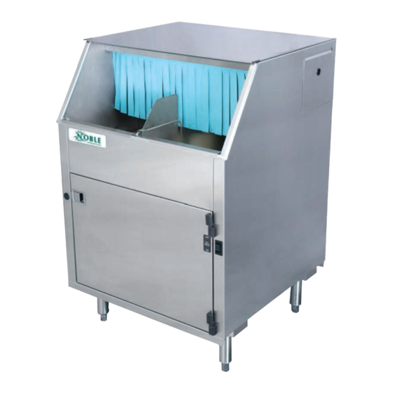
- Page 1 NOBLE GLASSWASHER DISHMACHINES INSTALLATION, OPERATION, AND SERVICE MANUAL NOBLE CG-1200 NOBLE CG-115 CG-1200/CG-115 Manual • 07610-004-26-27-F...
- Page 2 REVISION HISTORY Revision Revision Made by Applicable ECNs Details Letter Date 7-23-15 QOF-386 Initial release of manual. Added CG-115 and associated views, parts lists, and schematics to the 1-19-16 QOF-386 manual. 4-26-16 8379 Updated schematic on pg. 48. 9-21-16 Updated manual to new format. Removed “iodine”...
- Page 3 NOMENCLATURE CG-1200 208 V glasswasher dishmachine; chemical-sanitizing, carousel-type, electric tank heat, with detergent, rinse-aid, and sanitizer chemical feeder pumps. CG-115 115 V glasswasher dishmachine; chemical-sanitizing, carousel-type, electric tank heat, with detergent, rinse-aid, and sanitizer chemical feeder pumps. The manufacturer provides...
-
Page 4: Table Of Contents
TABLE OF CONTENTS GUIDES Symbols ............................1 Abbreviations & Acronyms ....................... 1 SPECIFICATIONS Machine Dimensions ........................2 Operating Parameters ........................3 Electrical Requirements ........................4 INSTALLATION Installation Instructions ........................5 Inspection......................... 5 Unpacking ........................5 Leveling..........................5 Plumbing .......................... 5 Pressure Regulator ...................... - Page 5 Wash Tank Heater Replacement ....................24 Thermostat Replacement ....................... 29 Wash Motor Replacement ......................32 PARTS Control Box Assembly - CG-1200 ....................35 Control Box Assembly - CG-115 ..................... 36 Outer Shell Assembly ........................37 Chemical Feeder Pump Assembly ....................38 Rinse Assembly ..........................
-
Page 6: Guides
GUIDES SYMBOLS - risk of injury to personnel. WARNING - risk of damage to equipment. CAUTION - risk of electrical shock. - reference data plate. - caustic chemicals. - ground wire. - lockout electrical power. - important note. NOTICE ABBREVIATIONS & ACRONYMS ANSI - American National Standards Institute GHT - Garden Hose Thread GPH - Gallons per Hour... -
Page 7: Specifications
MACHINE DIMENSIONS SPECIFICATIONS 25 1/4” LEGEND [641 mm] A - Electrical Connection 9 1/2” B - Water Inlet, Hot, 1/2” [241 mm] C - Water Inlet, Cold, 1/2” 5” D - Drain Connection, 1 1/2” [127 mm] All dimensions from the floor can be increased 1 1/4"... -
Page 8: Operating Parameters
OPERATING PARAMETERS SPECIFICATIONS Operating Capacity: CG-1200 CG-115 Glasses per Hour 1200 1200 Operating Cycle (Seconds): Total Cycle Time Tank Capacity (Gallons): Wash Pump Capacity (GPM): Water Temperatures (°F): Minimum Wash Temperature Minimum Rinse Temperature Other Water Requirements: Cold Water Flow Pressure (PSI) 20 ±... -
Page 9: Electrical Requirements
ELECTRICAL REQUIREMENTS SPECIFICATIONS NOTICE CG-1200 Electrical Characteristics All electrical ratings provided in this manual are for reference only. Always refer to the machine data plate to get exact electrical VOLTS information for this machine. All electrical work performed on machines should be done in accordance with applicable local, state, territorial, and national codes. -
Page 10: Installation Instructions
Cold water supply must be a minimum of 75 °F with a capacity of 180 GPH at 8-12 PSI. Hot water supply must be a minimum of 120 °F (CG-1200)/130 °F (CG-115) with a capacity of 10 GPH at 20 ± 5 PSI. Incoming hot and cold water service connections (supplied by customer) must be a 1/2”... -
Page 11: Pressure Regulator
INSTRUCTIONS INSTALLATION PRESSURE The manufacturer has an optional water pressure regulator to accommodate areas where water pressure fluctuates or is higher than the recommended pressure. Take REGULATOR care not to confuse static pressure with flow pressure: static pressure is line pressure in a “no flow”... -
Page 12: Electrical Power Connections
INSTRUCTIONS INSTALLATION ELECTRICAL POWER Electrical and grounding conductors must comply with the applicable portions of the National Electric Code ANSI/NFPA 70 (latest edition) and/or other electrical codes. CONNECTIONS The data plate is on the ride side of the door. Refer to the data plate for machine operating requirements, machine voltage, total amperage, and serial number. -
Page 13: Thermostats
INSTRUCTIONS INSTALLATION THERMOSTATS The thermostats on this dishmachine have been set at the factory. They should only be adjusted by an authorized service agent. CHEMICAL FEEDER CAUTION! Chlorine-based sanitizers can be detrimental to this machine if the chemical solution is too strong. See a chemical professional to EQUIPMENT ensure the dispenser is set-up correctly. -
Page 14: Operation
OPERATING INSTRUCTIONS OPERATION Before operating the unit, verify the following: PREPARATION 1. Wash strainer is clean and in place. 2. Rinse strainer is clean and in place. 3. The drain stopper is installed. 4. Chemical levels in chemical containers are correct. 1. -
Page 15: Ware Preparation
OPERATING INSTRUCTIONS OPERATION WARE Proper preparation of ware will help ensure good results and fewer re-washes. If not done properly, ware might not come out clean and the efficiency of the dishmachine PREPARATION will be reduced. Scraps should always be removed from ware before being loaded onto the carousel. -
Page 16: Shutdown & Cleaning
OPERATING INSTRUCTIONS OPERATION SHUTDOWN & 1. Turn power switch to the “OFF” 6. Remove and clean drain boards. position. CLEANING Disconnect electrical power at the breaker or 2. Ensure glasses are removed from disconnect switch and carousel. 7. Remove and clean rack cylinder. tag-out in accordance with procedures and codes. - Page 17 OPERATING INSTRUCTIONS OPERATION SHUTDOWN & 11. Remove rinse arm from manifold. 16. Remove wash arm from manifold. CLEANING 17. On all arms: remove end-caps, clean 12. Rotate top stop cap counter- with a brush, and flush with fresh clockwise until opening aligns with water.
-
Page 18: After Cleaning
OPERATING INSTRUCTIONS OPERATION AFTER 6. Insert middle of bottom rinse arm into 1. Spray or wipe out interior of machine. support bracket. CLEANING 2. Replace rinse strainer. CAUTION 7. Push bottom rinse arm onto manifold. CAUTION! Ensure all components are clean before replacing them in the machine! 3. - Page 19 OPERATING INSTRUCTIONS OPERATION AFTER 11. Turn top stop cap counter-clockwise 16. Replace rack cylinder. until opening aligns with wash arm CLEANING location on manifold. 17. Replace drain boards. 12. Insert middle of top rinse arm into support bracket. 18. Replace curtain. 13.
-
Page 20: Detergent Control
OPERATING INSTRUCTIONS OPERATION DETERGENT Detergent usage and water hardness are two factors that contribute greatly to how efficiently this dishmachine will operate. Using detergent in the proper amount can CONTROL become a source of substantial savings. A qualified water treatment specialist can determine what is needed for maximum efficiency from the detergent. -
Page 21: Maintenance Preventative Maintenance
PREVENTATIVE MAINTENANCE MAINTENANCE The manufacturer highly recommends that any maintenance and repairs not specifically PREVENTATIVE discussed in this manual be performed only by QUALIFIED SERVICE PERSONNEL. MAINTENANCE Performing maintenance on your dishmachine may void your warranty, lead to larger problems, or even cause harm to the operator. By following the operating and cleaning instructions in this manual, you should get the most efficient results from your machine. -
Page 22: Troubleshooting
COMMON PROBLEMS TROUBLESHOOTING WARNING! Inspection, testing, and repair of electrical equipment should only be performed by qualified service personnel. Certain procedures in this section require electrical tests or measurements while power is applied to the machine. Exercise extreme caution at all times. If test points are not easily accessible, disconnect WARNING power, attach test equipment, and reapply power to test. - Page 23 COMMON PROBLEMS TROUBLESHOOTING PROBLEM POSSIBLE CAUSE REMEDY 1. Loose wire connection to limit switch 1. Tighten wires. or relay. 2. Replace pump motor. 2. Faulty pump motor. Wash motor 3. If motor has correct incoming voltage, and the overload does not run; 3.
- Page 24 COMMON PROBLEMS TROUBLESHOOTING PROBLEM POSSIBLE CAUSE REMEDY 1. Power supply shorted to ground. 1. Check for loose wires/burned connection. Replace or repair as required. Machine keeps 2. Pump impeller jammed. tripping service 2. Disassemble and remove obstruction. breaker. 3. Wash pump motor faulty. 3.
- Page 25 COMMON PROBLEMS TROUBLESHOOTING PROBLEM POSSIBLE CAUSE REMEDY Sanitizer pump 1. Faulty sanitizer pump motor. 1. If you read line voltage at the sanitizer motor terminals doesn't run during the sanitizer feed cycle, replace the motor. during cycle or 2. Faulty prime switch. through prime 2.
-
Page 26: Service Procedures
SERVICE PROCEDURES SERVICE CHEMICAL FEEDER CAUTION! Many of the instructions and steps within this document require the use of tools. Only authorized personnel should ever perform PUMP MOTOR CAUTION any maintenance procedure on the dishmachine! REPLACEMENT PREPARATION • Power must be secured to the unit at the service breaker. Tag or lock-out the service breaker to prevent accidental or unauthorized energizing of the These machines come machine. - Page 27 SERVICE PROCEDURES SERVICE CHEMICAL FEEDER 4. Determine which motor you wish to replace, or which one you wish to start with. Trace the wire leading from the motor to its corresponding prime switch. PUMP MOTOR Trace the other wire from the motor to determine where it is connected. REPLACEMENT 5.
- Page 28 SERVICE PROCEDURES SERVICE CHEMICAL FEEDER 10. Once the screws are removed, the motor should drop away. PUMP MOTOR REPLACEMENT 11. Cut away any tie-wraps that are holding the power wires and remove the motor. 12. Take your new motor and attach new terminals to the wires as required. 13.
-
Page 29: Wash Tank Heater Replacement
SERVICE PROCEDURES SERVICE WASH TANK HEATER CAUTION! Many of the instructions and steps within this document require the use of tools. Only authorized personnel should ever perform REPLACEMENT CAUTION any maintenance procedure on the dishmachine! PREPARATION • Power must be secured to the unit at the service breaker. Tag or lock-out the service breaker to prevent accidental or unauthorized energizing of the These machines come machine. - Page 30 SERVICE PROCEDURES SERVICE WASH TANK HEATER 3. Remove the lower strainer. REPLACEMENT 4. Remove the ELAN thermostat using a phillips screwdriver. Either unplug the wires or cut the wire-tie and let the thermostat hang down out of the way. 5. Remove the thermostat bracket with the 3/8” nutdriver. 6.
- Page 31 SERVICE PROCEDURES SERVICE WASH TANK HEATER 8. Using a 1/2” socket or wrench, remove the heater mounting nuts. REPLACEMENT 9. Removing the heater might require that you reach into the wash tank, grasp it, and give it a push out of the wash tank. 10.
- Page 32 SERVICE PROCEDURES SERVICE WASH TANK HEATER 15. Place the heater wires on the heater and tighten the nuts down using the 3/8” nutdriver (Step 7 in reverse). REPLACEMENT 16. Using the torque wrench or a torque nutdriver (if available) torque the nuts holding the wires, jumpers, and bus bars to 16 in-lbs.
- Page 33 SERVICE PROCEDURES SERVICE WASH TANK HEATER 24. Replace the heater cover (Step 2 in reverse). REPLACEMENT 25. Replace the front door. AFTER MAINTENANCE ACTIONS • Service personnel might want to drain the machine and allow it to cool down. Secure power to the unit at the service breaker and then verify the torque of all fasteners covered in this instruction.
-
Page 34: Thermostat Replacement
SERVICE PROCEDURES SERVICE THERMOSTAT CAUTION! Many of the instructions and steps within this document require the use of tools. Only authorized personnel should ever perform REPLACEMENT CAUTION any maintenance procedure on the dishmachine! PREPARATION • Power must be secured to the unit at the service breaker. Tag or lock-out the service breaker to prevent accidental or unauthorized energizing of the These machines machine. - Page 35 SERVICE PROCEDURES SERVICE THERMOSTAT 3. Using the pair of needle-nose pliers (if necessary), disconnect the terminals from the thermostat probe. Be careful not to damage the terminals or the REPLACEMENT wires or they will have to be replaced. 4. Unplug all of the terminals/wires connected to the ELAN thermostat. 5.
- Page 36 SERVICE PROCEDURES SERVICE THERMOSTAT 8. Pull the thermostat probe out of the wash tank. REPLACEMENT 9. Place the new thermostat probe in the new imperial brass fitting provided in your kit. Use the 7/16” wrench to tighten it down after getting the fitting hand- tight in the tank.
-
Page 37: Wash Motor Replacement
SERVICE PROCEDURES SERVICE WASH MOTOR CAUTION! Many of the instructions and steps within this document require the use of tools. Only authorized personnel should ever perform REPLACEMENT CAUTION any maintenance procedure on the dishmachine! PREPARATION • Power must be secured to the unit at the service breaker. Tag or lock-out the service breaker to prevent accidental or unauthorized energizing of the These machines come machine. - Page 38 SERVICE PROCEDURES SERVICE WASH MOTOR 2. Using the 5/16” nutdriver, loosen the clamps on the suction hose. REPLACEMENT 3. Using the same nutdriver, loosen the disharge hose where it connects to the tub weldement. 4. Pull the discharge hose out and away from the tub. 5.
- Page 39 SERVICE PROCEDURES SERVICE WASH MOTOR 7. Turn the motor so that you will have access to the wiring cover on the back. Be careful not to pull or yank too hard as the motor is still connected to the REPLACEMENT unit by way of the power lines.
-
Page 40: Parts
CONTROL BOX ASSEMBLY - CG-1200 PARTS ITEM DESCRIPTION PART NUMBER Fitting 05975-011-49-03 Fitting 05975-011-65-51 Bracket 05700-003-56-00 Capacitor 05910-003-43-01 Ground Lug 05940-200-76-00 Separator 05940-500-09-61 Transformer 05950-011-61-67 Relay 05945-111-47-51 Contactor 05945-002-74-20 Access Panel 05700-003-55-38 Decal, Warning, Disconnect Power 09905-004-08-16 Decal, Caution 09905-011-68-99... -
Page 41: Control Box Assembly - Cg-115
CONTROL BOX ASSEMBLY - CG-115 PARTS ITEM DESCRIPTION PART NUMBER Fitting 05975-011-49-03 Fitting 05975-011-65-51 Ground Lug 05940-200-76-00 Separator 05940-500-09-61 Transformer 05950-002-16-78 Relay 05945-111-35-19 Contactor 05945-109-05-69 Access Panel 05700-003-55-38 Decal, Warning, Disconnect Power 09905-004-08-16 Decal, Caution 09905-011-68-99 Terminal Board 05940-002-78-97 Complete Assembly 05700-004-27-24 07610-004-26-27-F... -
Page 42: Outer Shell Assembly
OUTER SHELL ASSEMBLY PARTS ITEM DESCRIPTION PART NUMBER Outer Cover 05700-003-57-95 Bushing 05975-210-03-00 Access Cover 05700-003-58-73 Bullet Foot 05340-108-01-03 Switch Cover 05700-003-60-39 Power Switch 05930-011-61-69 Curtain 08415-003-60-35 Noble Decal 09905-003-35-11 Curtain Rod 05700-003-60-38 07610-004-26-27-F... -
Page 43: Chemical Feeder Pump Assembly
CHEMICAL FEEDER PUMP ASSEMBLY PARTS ITEM DESCRIPTION PART NUMBER 14 RPM Peri-pump 05700-003-87-08 Cover and Peri-pump Assembly 05700-003-55-29 Cover Only 05700-003-55-34 Sanitizer Tube Replacement Kit 06401-003-61-21 Rinse-aid Tube Replacement Kit 06401-003-61-22 Detergent Tube Replacement Kit 06401-003-61-23 Rinse-aid and Sanitizer Squeeze Tubes 05700-011-65-21 Detergent Squeeze Tube 05700-003-22-89... -
Page 44: Rinse Assembly
RINSE ASSEMBLY PARTS Vacuum Breaker Assembly 05700-003-55-31 Complete Bottom Inlet Manifold Assembly 05700-003-60-49 Rinse Tube 05700-003-49-32 Complete Plumbing Assembly 05700-003-58-77 *CG-115 has a different part number. See parts list on the next page. 07610-004-26-27-F... - Page 45 Adapter, 1/2" Barb x 1/4" 04730-004-55-02 Elbow, 90-degree 1/4" x 1/4" 04730-111-48-87 Fitting, 3/8" NPT x 1/2" Barbed 04730-002-18-54 Cover, Solenoid Assembly 05975-111-62-70 Solenoid Valve, CG-1200 04730-011-61-54 Solenoid Valve, CG-115 04730-002-75-48 3/8" Close Nipple 04730-002-18-00 Union, 3/8" NPT Straight Brass 04730-003-60-57 Tee, 3/8"...
-
Page 46: Wash System
WASH SYSTEM PARTS See previous page. Wash Tube 05700-003-49-32 Drain O-ring installs into fitting in bottom of wash tank. *CG-115 has a different part number. See parts list on the next page. 07610-004-26-27-F... - Page 47 Drain Stopper 05700-021-62-22 Hose, 3/4” OD 04720-003-57-29 Pump Suction Hose 05700-003-60-25 Pump Hose Connector 04730-003-40-64 Pump Discharge Hose 05700-003-59-96 Wash Pump, CG-1200 06105-003-44-22 Wash Pump, CG-115 06105-004-25-01 Bracket, Wash Pump 05700-003-56-41 Drain Weldment 05700-003-60-00 Hexnut, 1/2”-13 S/S 05310-011-72-58 Thermostat Probe 06685-004-17-26 Washer, 1/2”...
-
Page 48: Conveyor & Drive System
CONVEYOR & DRIVE SYSTEM PARTS *CG-115 has a different part number. See parts list on the next page. 07610-004-26-27-F... - Page 49 05700-004-35-13 Plate, Skid 09330-003-58-52 Drive Gear 09330-003-58-32 Washer 05330-003-41-75 Extension Spring 05340-003-41-83 Gear Motor Box 05700-003-48-87 Gear Motor, CG-1200 06105-003-44-23 Gear Motor, CG-115 06105-004-26-30 Gear Motor Box Cover 05700-003-48-57 Lock Nut, 6-32 05310-373-03-00 Switch Mounting Bracket 05700-003-60-13 Liquidtite Fitting 05975-011-49-03...
-
Page 50: Door Assembly
DOOR ASSEMBLY PARTS ITEM DESCRIPTION PART NUMBER Door Weldment 05700-002-24-40 Handle, Door Glasswasher 05340-001-96-30 Decal - Off/Fill/On 09905-011-61-70 Hinge 05340-021-62-04 Starwasher, External Tooth 05311-273-02-00 Screw 10-24 X 3/8 05305-173-03-00 Decal, Operating Instructions 09905-021-64-88 07610-004-26-27-F... -
Page 51: Schematics Cg-1200
CG-1200 SCHEMATICS 07610-004-26-27-F... - Page 52 CG-115 SCHEMATICS 07610-004-26-27-F...
- Page 54 NOBLE GLASSWASHER DISHMACHINES Noble Warewashing • Lancaster, Pennsylvania www.nobleproducts.biz For Service Call 1-888-800-5672 CG-1200/CG-115 Manual • 07610-004-26-27-F...
Need help?
Do you have a question about the CG-1200 and is the answer not in the manual?
Questions and answers