Sign In
Upload
Download
Table of Contents
Contents
Add to my manuals
Delete from my manuals
Share
URL of this page:
HTML Link:
Bookmark this page
Add
Manual will be automatically added to "My Manuals"
Print this page
×
Bookmark added
×
Added to my manuals
Manuals
Brands
Noble Manuals
Washer
UH30-FND
Installation, operation and service manual
Noble UH30-FND Installation, Operation And Service Manual
Hide thumbs
1
2
3
Table Of Contents
4
5
6
7
8
9
10
11
12
13
14
15
16
17
18
19
20
21
22
23
24
25
26
27
28
29
30
31
32
33
34
35
36
37
38
39
40
41
42
43
44
45
46
47
48
49
50
51
52
53
54
55
56
57
58
59
60
61
62
63
64
65
66
page
of
66
Go
/
66
Contents
Table of Contents
Troubleshooting
Bookmarks
Table of Contents
Table of Contents
Guides
Symbols
Abbreviations & Acronyms
Specifications
Machine Dimensions
Operating Parameters
Electrical Requirements
Installation
Installation Instructions
Inspection
Unpacking
Plumbing
Water Supply Connections
Pressure Regulator
Shock Absorber
Connecting the Drain Line
Plumbing Check
Electrical Power Connections
Voltage Check
Surrounding Area
Thermostats
Chemical Feeder Equipment
Preparing Chemical Feeder Pumps
Priming Chemical Feeder Pumps
Programming Chemical Feeder Pumps
Leveling
Heater Contactor Wires (UH30-FND Only)
Operation
Operating Instructions
Preparation
Filling the Wash Tub
Ware Preparation
Washing a Rack of Ware
Operational Inspection
Shutdown & Cleaning
Deliming
Detergent Control
Maintenance
Preventative Maintenance
Troubleshooting
Parts
UH30-FND Control Panel
UL30 Control Panel
UL30H Control Panel
UH30-FND Display Panel
UL30 Display Panel
UL30H Display Panel
Terminal Block Box
UH30-FND Chemical Feeder Pump
UH30-FND Chemical Feeder Pump Components
UL30/UL30H Chemical Feeder Pump
UL30/UL30H Peri-Pump Track
UH30-FND Plumbing
UL30/UL30H Plumbing
Plumbing Options
Vacuum Breaker
Wash Manifold
Motor & Pump
Rinse Arms & Wash Arms
Thermostat & Rinse Tank
Door
Miscellaneous Door Components
Frame & Panel Components
Miscellaneous Parts
Stands & Components
Go Box Kit
UL30H Optional Heater Components
UL30/UL30H Vacuum Switch
UL30/UL30H Vacuum Switch Install
Schematics
UH30-FND 208-240 V, 50/60 Hz, 1/3 Phase
UL30/UL30H 115 V, 50/60 Hz, 1 Phase
Advertisement
Quick Links
1
Operating Instructions
2
Troubleshooting
Download this manual
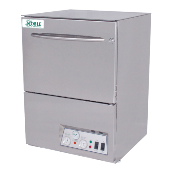
NOBLE UNDERCOUNTER DISHMACHINES
INSTALLATION, OPERATION,
AND SERVICE MANUAL
NOBLE UH30-FND
NOBLE UL30
NOBLE UL30H
Noble UH30-FND/UL30/UL30H Manual • 07610-004-37-38-G
Table of
Contents
Previous
Page
Next
Page
1
2
3
4
5
Advertisement
Table of Contents
Need help?
Do you have a question about the UH30-FND and is the answer not in the manual?
Ask a question
Questions and answers
Related Manuals for Noble UH30-FND
Dishwasher Noble UH30 Installation, Operation & Service Manual
Electrically heated undercounter dishmachines (65 pages)
Commercial Food Equipment Noble UL30 Instruction Manual
(2 pages)
Washer Noble UL30H Installation, Operation And Service Manual
(66 pages)
Washer Noble DG-E Installation, Operation And Service Manual
Glasswasher dishmachines (50 pages)
This manual is also suitable for:
Ul30
Ul30h
Table of Contents
Save PDF
Print
Rename the bookmark
Delete bookmark?
Delete from my manuals?
Login
Sign In
OR
Sign in with Facebook
Sign in with Google
Upload manual
Upload from disk
Upload from URL


Need help?
Do you have a question about the UH30-FND and is the answer not in the manual?
Questions and answers