
Related Manuals for Noble HT-180EC


Summary of Contents for Noble HT-180EC
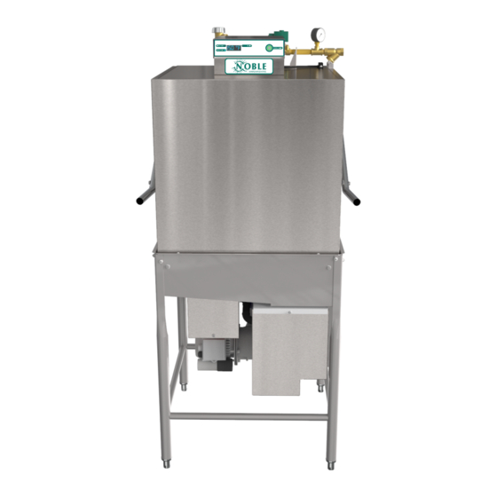
- Page 1 NOBLE DOOR-TYPE DISHMACHINES INSTALLATION, OPERATION, AND SERVICE MANUAL ° HT-180EC HT-180EC Manual • 07610-004-92-22-A...
- Page 2 REVISION HISTORY Revision Revision Made by Applicable ECNs Details Letter Date 10-9-20 Initial release of manual.
- Page 3 NOMENCLATURE HT-180EC1 Door-type dishmachine; ENERGY STAR qualified, ® electric-heated, high-temp, hot-water sanitizing, with booster heater, single-phase. HT-180EC3 Door-type dishmachine; ENERGY STAR qualified, ® electric-heated, high-temp, hot-water sanitizing, with booster heater, three-phase. The manufacturer provides technical support for all of the dishmachines detailed in this manual.
-
Page 4: Table Of Contents
TABLE OF CONTENTS GUIDES Symbols ............................1 Abbreviations & Acronyms ......................1 SPECIFICATIONS Dimensions ..........................2 Table Dimensions ........................3 Operating Parameters ........................ 4 Electrical Requirements ......................5 INSTALLATION Installation Instructions ....................... 6 Inspection ........................6 Unpacking........................6 Leveling ........................6 Plumbing........................6 Water Supply Connection ....................6 Pressure Regulator......................7 Shock Absorber ......................7 Connecting the Drain Line ...................7... - Page 5 TABLE OF CONTENTS OPERATION Detergent Control ........................15 Deliming ........................... 16 MAINTENANCE Preventative Maintenance ......................17 TROUBLESHOOTING Troubleshooting ........................18 PARTS Control Box ..........................20 Electrical Box ..........................22 Hood ............................24 Door & Arm ..........................26 Tub ............................28 Frame ............................
-
Page 6: Symbols
GUIDES GUIDES SYMBOLS - risk of injury to personnel. WARNING - risk of damage to equipment. CAUTION - risk of electrical shock. - caustic chemicals. - reference data plate. - lockout electrical power. - important note. NOTICE ABBREVIATIONS & ACRONYMS ANSI - American National Standards Institute Btu/Hr - British Thermal Units per Hour CFM - Cubic Feet per Minute... -
Page 7: Specifications
DIMENSIONS SPECIFICATIONS LEGEND A - Water Inlet (1/2” NPT) B - Electrical Connection Point C - Drain (1 1/2” NPT) can be increased 1 1/8" using the machine's adjustable feet. [102 mm] 25 1/4 [641 mm] 30 5/8 [779 mm] 16 7/8 3 1/4 15 1/2... - Page 8 TABLE DIMENSIONS SPECIFICATIONS CORNER INSTALLATION CORNER INSTALLATION 4 (102 mm) MIN ALIGN WITH TABLE - DISTANCE CAN VARY 8 7/16 4 (102 mm) MIN (214 mm) ALIGN WITH TABLE - 20 1/2” DISTANCE CAN VARY (521 mm) (762 mm) OPENING Distance from wall to rear rack rail.
-
Page 9: Operating Parameters
OPERATING PARAMETERS SPECIFICATIONS PERFORMANCE/CAPABILITIES Operating Capacity: Racks per Hour Dishes per Hour 1450 Glasses per Hour 2088 Minimum Operating Cycle (Seconds): Wash Time Rinse Time Dwell Time Total Cycle Time Tank Capacity (Gallons/Liters): Wash Tank 8.0/30.3 Rinse Tank 2.0/7.6 WATER REQUIREMENTS Minimum Wash Temperature (°F/°C) 150/66 Minimum Rinse Temperature (°F/°C) -
Page 10: Electrical Requirements
ELECTRICAL REQUIREMENTS SPECIFICATIONS Local codes may require more stringent protection than what is displayed here and on the data plate. Always verify with your electrical service contractor that your circuit protection is adequate and meets all applicable national and local codes. Numbers in this manual are for reference and may change without notice. -
Page 11: Installation
INSTRUCTIONS INSTALLATION INSPECTION Before installing the machine, check the packaging and machine for damage. If the packaging is damaged, the machine might also be damaged. If there is damage to both packaging and machine, do not throw away the packaging. The machine has been inspected and packed at the factory and is expected to arrive to you in new, undamaged Do not throw away condition. -
Page 12: Pressure Regulator
INSTRUCTIONS INSTALLATION PRESSURE The manufacturer recommends the installation of a pressure regulating valve (PRV) in the incoming water line to ensure proper flowrate at all times and offers these REGULATOR devices as options (see the Plumbing Options page). Do not confuse static pressure with flow pressure. Static pressure is the line pressure in a “no flow”... -
Page 13: Chemical Connections
INSTRUCTIONS INSTALLATION CHEMICAL Detergent Connect detergent by removing the bulkhead fitting on the back of the machine and CONNECTIONS replacing it with the appropriate dispensing equipment. Chemical connections should be made by the chemical supplier. Using deionized water or other aggressive fluids will result in corrosion and Detergent Probe failure of components and... -
Page 14: Electrical Power Connections
INSTRUCTIONS INSTALLATION ELECTRICAL POWER Electrical and grounding conductors must comply with the applicable portions of the National Electric Code ANSI/NFPA 70 (latest edition) and/or other electrical codes. CONNECTIONS The data plate is located on the right side of the machine. Refer to the data plate for machine operating requirements, machine voltage, total amperage, and serial number. -
Page 15: Voltage Check
INSTRUCTIONS INSTALLATION VOLTAGE CHECK Apply power to machine. Check the incoming power at the terminal block and ensure it corresponds with the voltage listed on the data plate. If not, contact a qualified service agency to examine the problem. Do not run the machine if voltage is too high or too low. -
Page 16: Operation
OPERATING INSTRUCTIONS OPERATION PREPARATION Before operating the machine, verify the following: 1. Tank is clean and free of debris. 2. Wash arms, rinse arms, and scrap screen are installed correctly. 3. Sump strainer and standpipe (located under scrap screen) are installed correctly and standpipe is down. -
Page 17: Warm-Up Cycles
OPERATING INSTRUCTIONS OPERATION WASHING A RACK OF 1. Ensure wash temperature has reached a minimum of 150 °F. 2. Open door completely. WARE 3. Slide rack of ware into the machine. 4. Close door and cycle starts automatically. LED ring on power button will turn green. - Page 18 OPERATING INSTRUCTIONS OPERATION SHUTDOWN & 4. Remove sump strainer and scrap screen. CLEANING 5. Use a hand-scraper to scrape foodsoil into a trash basket. 6. Rinse with pre-rinse hose and replace. 7. Remove all wash and rinse arms. 8. Remove the end-caps from the arms. 9.
- Page 19 OPERATING INSTRUCTIONS OPERATION SHUTDOWN & 12. Replace end-caps and ensure they have been tightened. CLEANING 13. Spray or wipe out interior of the machine. 14. Replace wash and rinse arms. 15. Ensure sump strainer and scrap screen are clean and securely in place. 16.
-
Page 20: Detergent Control
DETERGENT CONTROL OPERATION DETERGENT Detergent usage and water hardness are two factors that contribute greatly to how efficiently this machine will operate. Using detergent in the proper amount can CONTROL become a source of substantial savings. A qualified water treatment specialist can determine what is needed for maximum efficiency from the detergent. -
Page 21: Deliming
DELIMING OPERATION DELIMING Tank capacities of the machine can be found on the Operating Parameters page. 1. With power button on, raise door and lift standpipe to drain the machine. 2. Allow machine to completely drain. 3. Add deliming solution to tub per chemical supplier’s instructions. 4. -
Page 22: Maintenance
PREVENTATIVE MAINTENANCE MAINTENANCE PREVENTATIVE The manufacturer highly recommends that any maintenance and repairs not specifically discussed in this manual be performed only by qualified service personnel. MAINTENANCE WARNING! Unqualified personnel performing maintenance on the machine may void the warranty, lead to larger problems, or cause harm to the operator. WARNING Following the operating and cleaning instructions in this manual will result in the most efficient results from the machine. -
Page 23: Troubleshooting
TROUBLESHOOTING TROUBLESHOOTING WARNING! Inspection, testing, and repair of electrical equipment should only be performed by a qualified service technician. Many of the tests require that the machine have power to it and live electrical components be exposed. USE EXTREME CAUTION WHEN TESTING THE MACHINE. WARNING OBSERVATION POSSIBLE CAUSE... - Page 24 TROUBLESHOOTING TROUBLESHOOTING WARNING! Inspection, testing, and repair of electrical equipment should only be performed by a qualified service technician. Many of the tests require that the machine have power to it and live electrical components be exposed. USE EXTREME CAUTION WHEN TESTING THE MACHINE. WARNING OBSERVATION POSSIBLE CAUSE...
-
Page 25: Parts
CONTROL BOX PARTS Fuse, 6.3 A, Slow-acting Fuse, 3 A, Slow-blow 05920-004-90-73 05920-004-90-74 250 V, 5ST 6.3-R 250 V, 5TT-3-R Qty - 1 Qty - 5 07610-004-92-22-A... - Page 26 CONTROL BOX PARTS ITEM DESCRIPTION PART NUMBER Decal, Control Box 09905-004-85-62 I/O Module 05945-004-47-81 Cover, Control Box 05700-004-85-14 Screw, 10-32 x 1" 05305-002-19-42 Screw, 6-32 x 3/8" 05305-002-25-91 Locknut, 1/4-20 Hex with Nylon Insert 05310-374-01-00 Plug 05975-011-47-81 Door, Cycle Switch 05930-002-36-80 Fitting, 1/2"...
-
Page 27: Electrical Box
ELECTRICAL BOX PARTS 07610-004-92-22-A... - Page 28 ELECTRICAL BOX PARTS ITEM DESCRIPTION PART NUMBER Cover, Electrical Box 05700-004-85-07 Nut, 10-32 Hex 05310-004-40-48 Decal, Warning-Disconnect Power 09905-100-75-93 Washer, Flat 05311-173-01-00 Screw, 10-32 x 3/4" 05305-011-62-17 Ground Lug 05940-200-76-00 Screw, 10-32 x 1/2" 05306-004-42-04 Fitting, 1/2" Straight 05975-003-33-27 Thermostat, High-limit 05930-004-33-12 Bracket, High-limit 05700-004-36-37...
-
Page 29: Hood
HOOD PARTS 07610-004-92-22-A... - Page 30 HOOD PARTS ITEM DESCRIPTION PART NUMBER Bolt, 1/4-20 x 1/2" 05305-274-02-00 Guide, Hood 05700-004-90-99 Screw, 10-32 x 1/2” 05305-011-44-51 Support, Hood 05700-004-84-99 Guide, Hood, Rear 05700-004-87-24 Washer, 1/4-20 05311-174-01-00 Locknut, Low-profile, 10-32 05310-004-28-70 07610-004-92-22-A...
-
Page 31: Door & Arm
DOOR & ARM PARTS 07610-004-92-22-A... - Page 32 DOOR & ARM PARTS ITEM DESCRIPTION PART NUMBER Complete Cantilever Arm Assembly (items 1–5) 05700-004-85-10 Cantilever Arm Only 05700-001-21-00 Spring Pin, 1/4" x 1 1/8" 05315-407-06-00 Yoke Assembly 05700-000-75-77 Cotter Pin 05315-207-01-00 Yoke 05700-000-75-78 Clevis Pin, 5/16” x 1 3/8” 05315-700-01-00 Nylon Washer 05311-369-03-00...
-
Page 33: Tub
PARTS 07610-004-92-22-A... - Page 34 PARTS ITEM DESCRIPTION PART NUMBER Track Assembly 05700-002-01-00 Sump Strainer 05700-001-22-23 Bracket, Sump Strainer 05700-001-22-24 O-ring 05330-002-60-69 Bulk Head Plug 04730-609-05-00 Bolt, Hex 3/8-16 x 1 1/4" Long 05305-276-10-00 Lower Wash Manifold 05700-031-46-00 Gasket 05700-111-35-03 Scrap Screen 05700-003-07-76 Standpipe Lift 05700-002-91-54 05700-002-91-55 Standpipe Lift Support (Not Shown)
-
Page 35: Frame
FRAME PARTS ITEM DESCRIPTION PART NUMBER Bolt, 1/4-20 x 1/2” 05305-274-02-00 Locknut, 1/4-20 Hex with Nylon Insert 05310-374-02-00 Frame 05700-031-48-01 Bullet Foot 05340-108-01-03 Flanged Bullet Foot (Optional) 05340-002-34-86 07610-004-92-22-A... -
Page 36: Rinse Tank
RINSE TANK PARTS Complete Assemblies 208-230 V, 14 kW 70 ◦ Rise - 05700-004-43-33 460 V, 14 kW 70 ◦ Rise - 05700-004-53-22 ITEM DESCRIPTION PART NUMBER Tank, Rinse 05700-004-50-86 Heater, Rinse See Heaters page. Lockwasher, Split 5/16” 05311-275-01-00 Fitting, 1/4”, Brass Nut/Sleeve 05310-924-02-05 Gasket, Rinse Heater 05330-200-02-70... -
Page 37: Motors
MOTORS PARTS Complete Assemblies (See next page for parts.) 460 V: See Motor Rotation section. The models covered in this manual come supplied with various wash motor assemblies (a wash motor assembly includes the wash motor and the pump end), depending on the characteristics of the machine. To ensure you order the correct wash motor assembly for the model you are servicing, please refer to the following table: MODEL VOLTS... - Page 38 MOTORS PARTS Parts (See previous page for complete assemblies.) The models covered in this manual come supplied with various wash motors (see previous page), depending on the characteristics of the machine. To ensure you order the correct parts for the model you are servicing, please refer to the following table: ITEM DESCRIPTION...
-
Page 39: Heaters
HEATERS PARTS Volts Phase Wash Heater Rinse Heater (14 kW) 04540-121-47-39 04540-121-63-38 04540-121-47-39 04540-121-63-38 04540-121-47-39 04540-121-63-38 04540-121-47-39 04540-121-63-38 04540-121-47-39 04540-121-63-38 04540-121-47-39 04540-121-63-38 04540-121-47-39 04540-121-63-38 04540-121-47-39 04540-121-63-38 04540-002-44-31 04540-121-63-38 04540-002-43-09 04540-121-65-99 04540-121-63-39 04540-121-65-99 04540-121-63-39 Heater Phase Conversion Kit 06401-004-00-22 07610-004-92-22-A... -
Page 40: Plumbing
PLUMBING PARTS Complete Plumbing Assembly 05700-004-54-52 Top View Back View NOTICE When servicing plumbing components, take care not to damage the threads of each individual item. Damaged threads can cause leaks and loss of pressure, which could adversely affect the performance of the machine. It is strongly recommended that thread tape—used in conservative amounts—be applied to threads when joining components together. - Page 41 PLUMBING PARTS ITEM DESCRIPTION PART NUMBER Plumbing, Complete Assembly 05700-004-54-52 Plumbing, Inlet 05700-004-47-98 Vacuum Breaker, 1/2" Brass 04820-003-06-13 Plug, Rinse Injector, 1/8” Brass 04730-209-07-37 Casting, 1/2" Flanged Coupling 05700-004-47-97 Rinse Injector 05700-002-56-75 Gasket, Rinse Injector (Not Shown) 05330-111-42-81 Washer, 1/4-20 Hex with Nylon Insert 05311-174-01-00 Locknut, 1/4-20 Hex with Nylon Insert 05310-374-01-00...
-
Page 42: Plumbing Options
PLUMBING OPTIONS PARTS SHOCK ABSORBER (WATER ARRESTOR) OPTION Water Arrestor, 1/2” 06685-100-05-00 Tee, 1/2” x 1/2” x 1/2” 04730-211-27-00 Nipple, 1/2”, Close, Brass 04730-207-15-00 WATER TREATMENT OPTION Scaltrol System Replacement Cartridge 04730-003-05-76 (inspect at least every 6 months) RSC-100 PRESSURE REGULATING VALVE OPTION Pressure Gauge, 0-100 PSI 06685-111-88-34 Ball Valve, 1/4"... -
Page 43: Wash & Rinse Assemblies
WASH & RINSE ASSEMBLIES PARTS FINAL RINSE ARMS & MANIFOLD WASH ARMS & MANIFOLD 07610-004-92-22-A... - Page 44 WASH & RINSE ASSEMBLIES PARTS ITEM DESCRIPTION PART NUMBER Upper Manifold 05700-031-34-82 Nut, 3/8-16 Hex 05310-276-01-00 Lockwasher, 3/8" 05311-276-01-00 Bolt, Hex 3/8-16 x 7/8" 05306-011-36-95 O-ring 05330-111-35-15 Positioning Bracket, Manifold Tube 05700-011-34-63 Tube, Wash Manifold 05700-131-15-07 Gasket, Manifold 05700-111-35-03 Wash Arm 05700-004-13-13 Locknut, 1/4-20 Hex with Nylon Insert 05310-374-01-00...
-
Page 45: 460 V Machine Transformer Mounting Box
460 V MACHINE TRANSFORMER MOUNTING BOX PARTS 460 V Transformer 2 A Circuit Breaker 05950-111-65-93 05925-111-64-18 Transformer Mounting Bracket 05700-031-62-82 Transformer Mounting Box 05700-002-10-01 Transformer Mounting Box Top (Not Shown) 05700-000-78-53 07610-004-92-22-A... -
Page 46: Kits
KITS PARTS Call 1-880-800-5672 to order kits for HT-180EC and use the part numbers below: DESCRIPTION PART NUMBER Door Magnet Cover Kit 06401-004-07-73 Drain Water Tempering Kit 06401-004-85-80 Exhaust Fan Contactor Kit 05700-004-35-35 False Panel Kit 05700-002-75-59 Phase Conversion Kit... -
Page 47: Schematics
208/230/460 V, 50/60 HZ, 1-PH/3-PH SCHEMATICS HT-180EC 07610-004-92-22-A... - Page 48 NOBLE DOOR-TYPE DISHMACHINES Noble Warewashing • Lancaster, Pennsylvania www.nobleproducts.biz For Service Call 1-888-800-5672 HT-180EC Manual • 07610-004-92-22-A...
Need help?
Do you have a question about the HT-180EC and is the answer not in the manual?
Questions and answers