Table of Contents
Advertisement
INSTALLATION, OPERATION,
AND SERVICE MANUAL
with VENTLESS and ENERGY RECOVERY
January 12, 2016
07610-004-26-29-E
INSTALLATION MANUAL FOR EXPORT UNITS
SERVICE MANUAL FOR DOMESTIC UNITS
ELECTRICALLY HEATED MODELS:
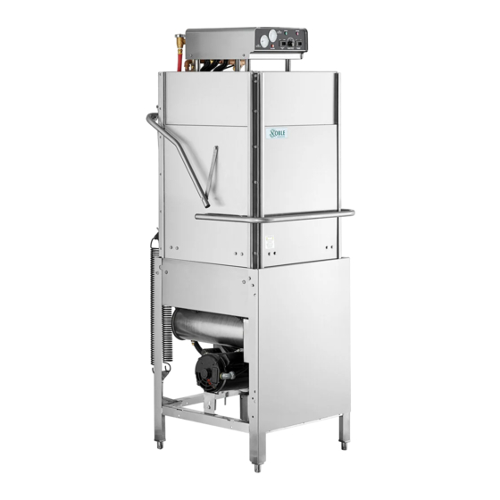
NOBLE HT-180 HH
NOBLE HT-180 HH
NOBLE SERIES
Upright Door Dishmachines
Noble Warewashing
Lancaster, Pennsylvania
www.nobleproducts.biz
Advertisement
Table of Contents

Related Manuals for Noble HT-180 HH


Summary of Contents for Noble HT-180 HH
- Page 1 Upright Door Dishmachines INSTALLATION, OPERATION, AND SERVICE MANUAL INSTALLATION MANUAL FOR EXPORT UNITS SERVICE MANUAL FOR DOMESTIC UNITS ELECTRICALLY HEATED MODELS: NOBLE HT-180 HH NOBLE HT-180 HH with VENTLESS and ENERGY RECOVERY Noble Warewashing January 12, 2016 Lancaster, Pennsylvania 07610-004-26-29-E...
- Page 4 REVISION HISTORY Revision Revision Applicable Made By Details Letter Date ECNs 07-24-15 Release to production. 10-08-15 Added HH ventless booster tank assembly on pg. 40. 11-10-15 Corrected part number for item #40 on pg. 37. 11-23-15 QOF-386 Replaced Plumbing Booster Inlet diagram, pg. 50. Changed item 12 on pg.
- Page 5 NOMENCLATURE FOR THE MODELS COVERED IN THIS MANUAL NOBLE HT-180 HH Door-type dishmachine; electrically-heated, high-temp, hot-water sanitizing, with booster heater. NOBLE HT-180 HH with VENTLESS AND ENERGY RECOVERY Door-type dishmachine; electrically-heated, high-temp, hot-water sanitizing, with booster heater and ventless heat recovery system.
-
Page 6: Table Of Contents
Y-Strainer Incoming Plumbing/Outlet Plumbing Assemblies ............43 Pressure Regulator Incoming Plumbing/Outlet Plumbing Assemblies ........46 Noble HT-180 HH with Ventless and Energy Recovery Plumbing Assemblies ......49 Drain Quench Assembly ......................51 1/2" Solenoid Valve & 1/2" NPT Vacuum Breaker Repair Parts Kits ........... 52 Wash &... - Page 7 SCHEMATICS Solid State (Top Mount Control Box) 208-230V, 50/60Hz, Single/Three Phase ......61 Noble HT-180 HH (Universal Timer) 208-230V, 50/60Hz, Single/Three Phase ......62 Solid State (Top Mount Control Box) 460V, 60Hz, Three Phase ..........63 Noble HT-180 HH (Universal Timer) 460V, 60Hz, Three Phase ..........64 Door Interlock Option ........................
-
Page 8: Specifications Operating Capacities
SPECIFICATIONS OPERATING CAPACITIES OPERATING CAPACITY HT-180 HH: WATER REQUIREMENTS: Selection A NOBLE HH & NOBLE HH Ventless: Racks per Hour Wash Temperature (minimum) (°F) Dishes per Hour 1325 Wash Temperature (minimum) (°C) Glasses per Hour 1908 Rinse Temperature (minimum) (°F) Rinse Temperature (minimum) (°C) -
Page 9: Electrical Requirements
110AMP 12kW@240V 110AMP 14kW@240V 125AMP 12kW@240V 60AMP 14kW@240V 70AMP 12kW@240V 70AMP 14kW@240V 80AMP 12kW@480V 30AMP 14kW@480V 35AMP NOBLE HT-180 HH VENTLESS: Rinse Heater Typical Electrical Volts Phase Freq Total Amps Ratings Circuit 15.4kW 110AMP 15.4kW 125AMP 15.4kW 70AMP 15.4kW 80AMP 15.4kW... -
Page 10: Machine Dimensions
SPECIFICATIONS DIMENSIONS (TOP MOUNT CONTROL BOX) Y-STRAINER OPTION 4 in [102 mm] LEGEND ON SIZE A - Drain 1 1/2" NPTF B - Water Inlet 3/4" NPTF CIAL CONNECTION) C - Electrical Connection OM FLOOR [641 mm] All vertical dimensions are ±1/2" due to adjustable bullet feet. - Page 11 SPECIFICATIONS DIMENSIONS (TOP MOUNT CONTROL BOX) PRESSURE REGULATOR OPTION LEGEND A - Drain 1 1/2" IPS B - Water Inlet 3/4" IPS C - Electrical Connection 4 [102mm] All vertical dimensions are +/- 1/2" due to adjustable bullet feet. 3 [76mm] 4 [102mm] 25 [637mm] 17 [432mm]...
- Page 12 SPECIFICATIONS DIMENSIONS (SIDE MOUNT CONTROL BOX) LEGEND A - DRAIN 1 1/2" IPS B - WATER INLET 3/4" IPS C - ELECTRICAL CONNECTION All dimensions are in inches. All vertical dimensions are +/- 1/2" due to adjustable 4 [102mm] bullet feet. 3 [76mm] 15 1/4 [388mm] 25 [637mm]...
- Page 13 SPECIFICATIONS DIMENSIONS (LEFT SIDE CONTROL BOX) LEGEND A - Drain 1 1/2” B - Water Inlet 3/4” C - Electrical Connection 4 [102mm] All vertical dimensions are +/- 1/2” due to adjustable bullet feet. 15 1/4 [388mm] 3 [76mm] 4 [102mm] 25 [637mm] 4 [102mm] 1 [25mm]...
- Page 14 SPECIFICATIONS DIMENSIONS (VENTLESS HEAT RECOVERY) 101mm) LEGEND A) DRAIN 1 B) WATER INLET C) ELECTRICAL CONNECTIONS All vertical dimensions are ± 1/2" due to adjustable bullet feet 3 (76mm) (134mm) (637mm) (639mm) 17 (432mm) (79mm) 93 (2362mm) 88 (2235mm) 73 (1856mm) 34 (861mm) (298mm) (387mm)
-
Page 15: Table Dimensions
SPECIFICATIONS TABLE DIMENSIONS NOTE: Please remove the front dress panel from the dishmachine if mounting dishmachine for a corner installation and attaching side tables. Corner installation will trap panel making it diffi cult to remove. LETTER DIM (IN) DIM (CM) 4”... -
Page 16: Installation & Operation Installation Instructions
SPECIFICATIONS INSTALLATION INSTRUCTIONS VISUAL INSPECTION: Before installing unit check container and machine for damage. A damaged container may be an indication of damage to the machine. If there is any type of damage to both container and unit, do not throw away the container. -
Page 17: Electrical Installation Instructions
INSTALLATION & OPERATION INSTALLATION INSTRUCTIONS The water supply line is to be capable of 20±5 PSI “fl ow” pressure at the recommended temperature indicated on the data plate. Take care not to confuse static pressure with fl ow pressure: Static pressure is line pressure in a “no fl ow” condition (all valves and services are closed);... -
Page 18: Noble Ht-180 Hh With Ventless And Energy Recovery Mounting
INSTALLATION & OPERATION VENTLESS HEAT RECOVERY MOUNTING INSTRUCTIONS Due to shipping constraints the NOBLE HT-180 High Hood is shipped dissembled, you should receive two pieces. Heat Recovery Unit Base Unit Fully Assembled Unit The heat recovery unit box is located inside the dishmachine shipping box. - Page 19 INSTALLATION & OPERATION VENTLESS HEAT RECOVERY MOUNTING INSTRUCTIONS Locate and remove the four 1/4-20 bolts using a 7/16 wrench. These are located in top left and right corner of the unit. Lift the heat recovery unit up and over the lower air inlet, then align and slide unit onto the lower air inlet.
- Page 20 INSTALLATION & OPERATION VENTLESS HEAT RECOVERY MOUNTING INSTRUCTIONS Connect pressure gauge with a 9/16 wrench. Connect the two hoses using an adustable wrench. The hoses are cut to length and will only reach their intended connection point. A. Connect the Gauge B.
- Page 21 INSTALLATION & OPERATION VENTLESS HEAT RECOVERY MOUNTING INSTRUCTIONS Locate the wire connectors at the top of the unit and connect the white and black wires from the base unit. Slide wire into the hole and push the lever down Tidy up the wires and lock them in place with the P-Clamp on the top of the unit. P-Clamp Now you have a fully assembled unit.
-
Page 22: Operating Instructions
INSTALLATION & OPERATION OPERATING INSTRUCTIONS The Conserver XL-E Series CAM timer is a 1 minute, 30 second, 8-CAM timer (CAM 8 is a spare) that controls the operation of the dishmachine. The following is a description of the set points for each CAM and the function of each switch. CAM 1 is a cut CAM with a single notch that serves as the cycle/reset control. - Page 23 INSTALLATION & OPERATION OPERATING INSTRUCTIONS SHUTDOWN AND CLEANING: At the end of the workday, close the doors. When the unit completes the cycle, turn the power switch to the OFF position and open the door. Remove and clean the pan strainer. Remove the drain stopper from the tub and allow the tub to drain (NOTE: The wash tank water will be hot so caution is advised).
- Page 24 INSTALLATION & OPERATION DETERGENT CONTROL DETERGENT CONTROL: Detergent usage and water hardness are two factors that contribute greatly to how effi ciently this dishmachine will operate. Using detergent in the proper amount can become a source of substantial savings. A qualifi...
-
Page 25: False Panel Installation
INSTALLATION & OPERATION FALSE PANEL INSTRUCTIONS Rack rail removed and repositioned for a corner operation. False panel positioned in unit 1. Remove the rack assembly from the dishmachine. 2. The false panel will mount inside of the dishmachine. 3. Position the panel in the dishmachine on the side to be closed. 4. -
Page 26: Preventative Maintenance
PREVENTATIVE MAINTENANCE Noble Warewashing highly recommends that any maintenance and repairs not specifi cally discussed in this manual should be performed by QUALIFIED SERVICE PERSONNEL ONLY. Performing maintenance on your dishmachine may void your warranty if it is still in effect. By following the operating and cleaning instructions in this manual, users should get the most effi... -
Page 27: Troubleshooting
TROUBLESHOOTING PROBLEM POSSIBLE CAUSE REMEDY Dishmachine runs Machine is in delime mode. Change operation mode from DELIME to NORMAL position. continuously in the wash cycle. Wash cycle delay timer is faulty. During the wash cycle, the cam timer will move for the fi rst 30 seconds of the wash cycle. - Page 28 TROUBLESHOOTING PROBLEM POSSIBLE CAUSE REMEDY Wash water is not Faulty wash heater. Check element for continuity; if open, replace heater. reaching required temperature. Misadjusted/faulty thermostat(s). Verify operation and setting of thermostats; replace if necessary. Wash thermometer is defective. Replace thermometer. Doors will not close Improper spring tension.
-
Page 29: Parts
PARTS TOP MOUNTED CONTROL BOX ASSEMBLY 07610-004-26-29-E... - Page 30 PARTS TOP MOUNTED CONTROL BOX ASSEMBLY (CONTINUED) 07610-004-26-29-E...
- Page 31 PARTS TOP MOUNTED CONTROL BOX ASSEMBLY (CONTINUED) ITEM DESCRIPTION PART NUMBER Control Box Weldment 05700-003-30-14 Timer Bracket 05700-003-02-08 Lock Nut 6-32 05310-373-03-00 Heater Contactor 05945-109-01-69 Terminal Block 05940-011-48-27 Lock Nut 10-24 05310-373-01-00 Contactor, Wash Motor 05945-002-74-20 Relay 05945-111-47-51 Relay (415V, 3PH, 5 Wire Only) 05945-111-89-75 Light, Green 05945-111-44-43...
- Page 32 PARTS TOP MOUNTED CONTROL BOX ASSEMBLY (CONTINUED) ITEM DESCRIPTION PART NUMBER Fuse Holder, 6 Pole 05920-002-42-13 Screw, 6-32 x 3/8" with Ext. Tooth Washer 05305-002-25-91 Decal, Dispenser Connection 09905-003-34-09 Timer, Universal 05945-003-33-09 Timer, Universal Fused (Alternate) 05945-003-75-23 Locknut, 10-32 05310-373-02-00 Screw 10-32 x 1"...
-
Page 33: Side Mounted Control Box Assembly (Universal Timer)
PARTS SIDE MOUNT UNIVERSAL TIMER CONTROL BOX ASSEMBLY 07610-004-26-29-E... - Page 34 PARTS SIDE MOUNT UNIVERSAL TIMER CONTROL BOX ASSEMBLY (CONTINUED) ITEM DESCRIPTION PART NUMBER Bracket, Electrical Box Mounting 05700-002-18-48 Locknut, 1/4"-20 S/S Hex with Nylon Insert 05310-374-01-00 Washer, 1/4"-20 I.D. S/S 05311-174-01-00 Control Box Weldment, Right Hand 05700-002-06-48 Control Box Weldment, Left Hand 05700-002-23-08 Contactor, 4 Pole, 220V, 1 Phase 05945-109-01-69...
- Page 35 PARTS SIDE MOUNT UNIVERSAL TIMER CONTROL BOX ASSEMBLY (CONTINUED) ITEM DESCRIPTION PART NUMBER Cover, Control Box Weldment 05700-002-06-52 Bolt, 10-32 x 1/2" Slotted Truss 05305-173-04-00 Switch, Rotary Selector 05930-003-97-61 Switch, Operation 05930-301-53-00 Decal, Control Box Cover 09905-003-97-39 Light, Red 05945-504-07-18 Light, Green Indicator 05945-504-08-18 Light, Amber...
-
Page 36: Side Mounted Control Box Assembly (Mechanical Timer)
PARTS SIDE MOUNT MECHANICAL TIMER CONTROL BOX 07610-004-26-29-E... - Page 37 PARTS SIDE MOUNT MECHANICAL TIMER CONTROL BOX (CONTINUED) ITEM DESCRIPTION PART NUMBER Contactor, 4 Pole, 220V, 1 Phase 05945-109-01-69 Liquid Level Control 06680-200-08-21 Decal, 120°F Wash/Rinse (not shown) 09905-002-82-46 Relay, 240V, 50/60Hz, Top Mount 05945-002-47-74 Timer, Cam/Mechanical 05945-303-31-00 Contactor, 2 Pole, 220V, 20 Amp (208-230V Unit only) 05945-002-74-20 Bolt, 10-32 x 1/2"...
-
Page 38: Hood Assembly
PARTS HOOD ASSEMBLY 07610-004-26-29-E... - Page 39 PARTS HOOD ASSEMBLY ITEM DESCRIPTION PART NUMBER Hood Weldment 05700-003-05-67 Hood Support Assembly 05700-004-13-45 Left Back Inner Door Guide 05700-031-76-34 Right Back Outer Door Guide 05700-031-76-32 Right Back Inner Door Guide 05700-031-76-35 Left Back Outer Door Guide 05700-031-76-33 Locknut, 1/4-20 Hex w/Nylon Insert 05310-374-01-00 Washer, S/S 1/4-20 I.D.
-
Page 40: Cantilever Arm/Door Assemblies
PARTS CANTILEVER ARM/DOOR ASSEMBLIES ITEM DESCRIPTION PART NUMBER Cantilever Arm 05700-004-14-29 Sleeve, Cantilever Arm 05700-000-85-69 Screw, 1/4"-20 x 1 1/2" Long Hex Head 05305-274-23-00 Washer, 1/4" I.D. S/S 05311-174-01-00 Locknut, 1/4"-20 S/S Low Profi le with Nylon Insert 05310-374-02-00 Plug, Cantilever 05340-011-35-00 Connecting Link 05700-021-92-45... - Page 41 Door Stop Magnet Weldment (not shown) 05700-002-01-27 Magnet (not shown) 05930-111-69-25 End Cap (not shown) 05700-011-60-92 Bumper, Noble HT-180 HH Door 05700-004-14-25 Screw, 1/4"-20 x 5/8" 05305-274-24-00 Locknut, 1/4"-20 S/S Hex with Nylon Insert 05310-374-01-00 Screw, 1/4"-20 x 1/2" Long Hex Head...
-
Page 42: Tub Assembly
PARTS TUB ASSEMBLY 10, 11 Solid State Thermostat 14, 11 31, 30 22 23 27, 28 W-BRACKET, MOTOR MOUNT INNER 05700-004-13-09 F-BRACKET, MOTOR MOUNT OUTER 05700-004-13-08 LOCKNUT, 1/4-20 05310-374-01-00 BOLT, 1/4-20 X 1/2" 05305-274-02-00 WASHER, 1/4" I.D.X 3/4" O.D. 05311-011-76-30 07610-004-26-29-E... - Page 43 PARTS TUB ASSEMBLY (CONTINUED) ITEM DESCRIPTION PART NUMBER Tub Weldment 05700-002-12-59 Rack Assembly 05700-002-01-00 Bulk Head Plug 04730-609-05-00 See Page Entitled “Wash Motors” Gasket 05700-111-35-03 O-ring 05330-400-05-00 Bolt, Hex 3/8”-16 x 1 1/4" Long 05305-276-10-00 Lower Wash Manifold Weldment 05700-031-46-00 Suction Strain Weldment 05700-001-22-23 Suction Strain Bracket...
- Page 44 PARTS TUB ASSEMBLY (CONTINUED) ITEM DESCRIPTION PART NUMBER Cover, Wash Heater 05700-031-47-57 Decal, Warning-Disconnect Power 09905-100-75-93 Decal, High Limit 09905-011-84-32 Thermostat Bracket 05700-011-81-64 Wash Heater Gasket 05330-011-47-79 Thermostat, Regulating 05930-510-02-79 Kit, Wash Thermostat Replacement (Includes: thermostat, brass fi tting, 2 jumper wires & instruc- 06401-003-18-22 tions) Thermostat, High Limit...
-
Page 45: Frame Assembly
PARTS FRAME ASSEMBLY Cover, Front Panel 05700-002-01-42 Bullet Foot 05340-108-02-06 Bullet Foot 05340-002-14-55 Flange Feet 05340-002-01-15 07610-004-26-29-E... -
Page 46: Rinse Tank Assembly
PARTS RINSE TANK ASSEMBLY COMPLETE ASSEMBLIES 230V, 14KW 70 ◦ Rise - P/N 06401-004-19-57 240V, 12 KW 40 ◦ Rise - P/N 06401-004-19-55 410V, 12KW 40 ◦ Rise - P/N 06401-004-19-56 415V, 12KW 40 ◦ Rise - P/N 06401-004-19-54 SEE PAGE ENTITLED "WASH HEATERS/RINSE HEATERS."... -
Page 47: Ventless Rinse Tank Assembly
PARTS PARTS PARTS MOTORS — WASH HEATERS — RINSE HEATERS VENTLESS RINSE TANK ASSEMBLY COMPLETE ASSEMBLY P/N - 05700-004-21-95 (2 PLC'S) (2 PLC'S) (8 PLC'S) (8 PLC'S) (3 PLC'S) ITEM DESCRIPTION PART NUMBER Booster Tank Weldment - Ventless HH 05700-004-21-83 Gasket, Wash Heater 05330-011-47-79 Heater, 10KW 230V... -
Page 48: Wash Motor
Different manufacturers use different wire color codes and your new motor may not connect using the same wires. Always refer to the diagrams on the motor you are installing. If the schematics have been removed from the motor you are installing, contact Noble Warewashing technical support immediately. 07610-004-26-29-E... - Page 49 MOTORS — WASH HEATERS — RINSE HEATERS The Noble models covered in this manual come supplied with various heaters, depending on the characteristics of the machine. To ensure that the correct heater is ordered for the model being serviced, refer to the following table: 40°F RISE...
-
Page 50: Y-Strainer Incoming Plumbing/Outlet Plumbing Assemblies
PARTS Y-STRAINER INCOMING & OUTLET PLUMBING ASSEMBLIES 07610-004-26-29-E... - Page 51 When servicing plumbing components, take care not to damage the threads of each individual item. Damaged threads can cause leaks and loss of pressure, which could adversely effect the performance of the NOBLE HT-180 HH dishmachine. It is strongly recommended that tefl...
- Page 52 PARTS Y-STRAINER INCOMING & OUTLET PLUMBING ASSEMBLIES (NOBLE HT-180 HH) ITEM DESCRIPTION PART NUMBER Tee, Brass, 1/2" x 1/2" x 1/4" NPT 04730-411-25-01 Adapter, 1/2” MNPT x Cu Male 04730-011-59-53 Strainer, Y 1/2” 04730-217-01-10 Valve, Ball, Bronze, 1/4" NPT 04810-011-72-67 Adapter, 1/2”...
-
Page 53: Pressure Regulator Incoming Plumbing/Outlet Plumbing Assemblies
PARTS PRESSURE REGULATOR INCOMING & OUTLET PLUMBING ASSEMBLIES INCOMING PLUMBING OUTLET PLUMBING 07610-004-26-29-E... - Page 54 PARTS PRESSURE REGULATOR INCOMING & OUTLET PLUMBING ASSEMBLIES (CONTINUED) ITEM DESCRIPTION PART NUMBER Water Pressure Regulator, 3/4" NPT 06685-011-58-22 Valve, Ball, 1/4" NPT 04810-011-72-67 Gauge, Pressure, 0-100 PSI 06685-111-88-34 Nipple, Close 3/4" NPT 04730-207-34-00 Tee, Brass, 3/4" NPT x 3/4" NPT x 1/4" NPT 04730-211-04-00 Valve, Solenoid, 3/4"...
- Page 55 PARTS PRESSURE REGULATOR INCOMING PLUMBING (NOBLE HT-180 HH) ITEM DESCRIPTION PART NUMBER Vacuum Breaker, 3/4" NPT 04820-002-53-77 Elbow, Brass, Street, 3/4" NPT 04730-206-04-34 Nipple, Brass, 3/4" NPT x 3" Long 04730-011-38-29 Union, 3/4" NPT, Brass with O-Ring 05700-002-63-79 Nipple, Close, Brass, 3/4" NPT 04730-207-34-00 Valve, Solenoid, 3/4"...
-
Page 56: Noble Ht-180 Hh With Ventless And Energy Recovery Plumbing Assemblies
PARTS INCOMING PLUMBING (NOBLE HT-180 HH VENTLESS) RINSE INJECTOR 09515-004-22-73 ITEM DESCRIPTION PART NUMBER Vac Breaker 1/2 Brass 04820-003-06-13 Elbow, 90 Degree 1/2 Street Brass 04730-206-08-00 W-Plumbing, Rinse Injector 05700-004-19-83 A-Plumbing, Outlet w/ Heat Exc. 05700-004-19-12 Hose, 1/2" ID X 24" LG Red 05700-004-19-89 Hose, 1/2"... - Page 57 PARTS INCOMING PLUMBING (NOBLE HT-180 HH VENTLESS) ITEM DESCRIPTION PART NUMBER Bushing, Hex 3/4"M to 1/2" Brass 04730-002-56-27 Elbow, 3/4 Street Brass 90 Degrees 04730-206-04-34 Union, 1/2" X 1/2" Brass 04730-003-62-44 Tee, 1/2 FNPT X 1/2 FNPT 1/4 FNPT 04730-002-22-56 Nipple, Brass 1/2"...
-
Page 58: Drain Quench Assembly
PARTS DRAIN QUENCH ASSEMBLY Elbow, 1-1/2” 90 Street 04730-206-32-00 Drain Quench Assembly 06401-002-59-52 Nipple, 1-1/2” NPT 04730-207-40-00 Modified Compression Fitting Lid, Drain Quench 05700-001-16-52 05700-002-67-16 Thermostat 05930-003-13-65 Solenoid Valve Reducer, 1-1/2” x 1/4” 04810-100-09-18 04730-002-55-76 To Dishmachine Drain To Cold Water Supply Tee, 1-1/2”... -
Page 59: 1/2" Solenoid Valve & 1/2" Npt Vacuum Breaker Repair Parts Kits
PARTS 3/4" SOLENOID VALVE & 3/4" VACUUM BREAKER REPAIR PARTS KITS Screw Cap Screw Data Plate Coil & Housing Data Plate Valve Bonnet Spring 06401-003-07-40 Plunger Cap Retainer 06401-003-07-40 O-Ring O-Ring Diaphragm 06401-003-07-42 Retainer Plunger Diaphragm 06401-003-07-42 Components of Repair Kit 06401-003-06-24 Body Screen... -
Page 60: Wash & Rinse Arm/Manifold Assemblies
PARTS WASH & RINSE ARM/MANIFOLD ASSEMBLIES 2, 3, 4 9, 18 6, 18 17, 8 2, 3, 19 07610-004-26-29-E... - Page 61 PARTS WASH & RINSE ARM/MANIFOLD ASSEMBLIES (CONTINUED) ITEM DESCRIPTION PART NUMBER Upper Manifold 05700-031-34-82 Nut, 3/8"-16 S/S Hex 05310-276-01-00 Lockwasher, 3/8" 05311-276-01-00 Bolt, Hex 3/8"-16 x 7/8" Long 05306-011-36-95 O-Ring 05330-111-35-15 Positioning Bracket, Manifold Tube 05700-011-34-63 Tube, Wash Manifold 05700-031-92-58 Gasket, Manifold 05700-111-35-03 Wash Arm Assembly...
-
Page 62: Transformer Mounting Box Components
PARTS 460 VOLT MACHINE TRANSFORMER MOUNTING BOX 07610-004-26-29-E... -
Page 63: Exhaust Fan Control
PARTS EXHAUST FAN CONTROL OPTION 07610-004-26-29-E... -
Page 64: Noble Ht-180 Hh With Ventless And Energy Recovery Assembly
PARTS NOBLE HT-180 HH VENTLESS AND ENERGY RECOVERY SYSTEM ASSEMBLY 07610-004-26-29-E... - Page 65 PARTS NOBLE HT-180 HH VENTLESS AND ENERGY RECOVERY SYSTEM ASSEMBLY ITEM DESCRIPTION PART NUMBER Coil, Heat Exchanger 04420-004-19-61 Inlet, Cold Water 05700-004-19-01 Ring, Water Inlet 05700-004-19-24 Plate, Fan Mounting 05700-004-18-07 Upper Shroud 05700-004-18-06 Exhaust Box 05700-004-18-04 Gasket, Heat Exchanger 05330-004-18-22...
-
Page 66: Ventless Door Interlock
PARTS NOBLE HT-180 HH VENTLESS DOOR INTERLOCK ITEM DESCRIPTION PART NUMBER Guide Block, Door Lock 09330-004-22-72 F-Cover, Door Lock Mounting 05700-004-22-80 W-Rod, Interlock Weldment 05700-004-23-15 Soleniod, Horizontal 1" Push 04820-004-24-11 Spring, Comp. 05935-004-24-10 W-Base, Door Interlock Box 05700-004-24-25 Screw 3/8 Pan Head... -
Page 67: Standard Door Interlock Instructions
DOOR INTERLOCK/DOOR OVERRIDE INSTRUCTIONS The following instructions are for NOBLE HT-180 HH models equipped with the Door Interlock option. These instructions should only be used if the door interlock fails to unlatch and the doors are unable to be opened. - Page 68 PARTS SOLID STATE NOBLE HT-180 HH (TOP MOUNT CONTROLS), 208-230V, 60HZ, 1 & 3 PHASE 07610-004-26-29-E...
-
Page 69: Electrical Schematics
ELECTRICAL SCHEMATICS NOBLE HT-180 HH (UNIVERSAL TIMER), 208-230V, 60HZ, 1 & 3 PHASE 07610-004-26-29-E... - Page 70 ELECTRICAL SCHEMATICS SOLID STATE NOBLE HT-180 HH (TOP MOUNT W/CYCLE SWITCHES), 460V, 60HZ, 3 PHASE 07610-004-26-29-E...
- Page 71 ELECTRICAL SCHEMATICS NOBLE HT-180 HH (UNIVERSAL TIMER), 460V, 60HZ, 3 PHASE 07610-004-26-29-E...
- Page 72 ELECTRICAL SCHEMATICS NOBLE HT-180 HH 208-230V, 60HZ, 1 & 3 PHASE 07610-004-26-29-E...
- Page 73 ELECTRICAL SCHEMATICS NOBLE HT-180 HH, 460V, 60HZ, 3 PHASE 07610-004-26-29-E...
- Page 74 ELECTRICAL SCHEMATICS: OPTIONS DOOR INTERLOCK OPTION 07610-004-26-29-E...
- Page 75 ELECTRICAL SCHEMATICS: OPTIONS EXHAUST FAN HOOKUP/DRAIN QUENCH OPTIONS 07610-004-26-29-E...
- Page 76 Noble Warewashing • Lancaster, Pennsylvania www.nobleproducts.biz NOBLE HT-180 HH Series Installation, Operation, and Technical Manual 07610-004-26-29-E Issued: 07/23/2015 Revised: 01/12/2016...
Need help?
Do you have a question about the HT-180 HH and is the answer not in the manual?
Questions and answers