Table of Contents
Advertisement
Quick Links
Advertisement
Table of Contents

Related Manuals for Chauvin Arnoux C.A 8230


Summary of Contents for Chauvin Arnoux C.A 8230
- Page 1 C.A 8230 SINGLE-PHASE POWER QUALITY ANALYSER ENGLISH Operating manual...
- Page 2 In conformity with directive WEEE 2002/96/EC. You have just purchased a C.A 8230 single-phase power quality analyser, and we thank you for your confidence. For best results with your instrument: Read this operating manual carefully, Observe the precautions for use.
-
Page 3: Table Of Contents
Waveforms......... 15 11. Use...........36 Max - Min ........... 16 11.1 Starting ............36 Simultaneous display ......16 11.2 Configuring the C.A 8230 ......36 Phase rotation ........17 11.3 Placing the cords .......... 37 11.4 Measurement of waveforms ....37 11.5 Detection of alarms... - Page 4 11.9 Transferring data to a PC......... 38 11.10 Erasure of the data ........38 11.11 Stopping ............. 38 11.12 Power supply of the C.A 8230 ....38 12. Maintenance........39 12.1 Important recommendation......39 12.2 Recharging the battery ......... 39 12.3 Cleaning the housing ........39 12.4 Metrological check ........
-
Page 5: Introduction
Measurement of the angles of harmonics, up to The C.A 8230 can be used not only for a snapshot order 50, and of their levels (with respect to the of the main characteristics of a network, but also to fundamental) in voltage, current, or power. -
Page 6: Presentation
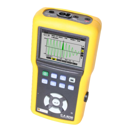
Display of measurements linked to powers and energies. Display of curves linked to harmonics: Screen grab for later viewing (press for Figure 1: Overall view of the C.A 8230. more than 2 seconds) or management of screen grabs. Item Function See §... -
Page 7: Display Screen
The PC to C.A 8230 direction is used to transfer any 3.5 Display screen upgrades of the embedded software and certain This colour liquid-crystal display unit (320x240 configurations. pixels) is used to view the measurements and the The transfer rate is determined automatically by the parameterising menus. -
Page 8: Prop
3.10 Prop are recharged using the mains power unit supplied with the instrument. It is connected to the C.A 8230 A retractable prop (Figure 4, item 4) on the back of using the jack (Figure 3, item 1). Use only the mains the C.A 8230 holds the instrument in position 30°... -
Page 9: Abbreviations
3.11.2 Display functions See Vcf and Acf. • Bar charts of harmonics. DC component of the current and of the • "Inrush" recording (starting current): display of voltage (phase-to-phase in balanced 3 φ parameters useful for studying the starting of a mode). -
Page 10: Key (Configuration)
4. KEY (Configuration) This key is used to configure the C.A 8230: the 4.2 Display language instrument must be parameterised before it is first The display language is chosen from among the six used, subsequently necessary; languages available (French, English, German, configuration remains in memory even when the Italian, Spanish, and Portuguese). -
Page 11: Contrast / Brightness
Red, Dark red, Dark brown, Brown, Orange, Yellow, Green, Dark green, Blue, Dark blue, Light grey, Connection Grey, Dark grey, Black. The display looks like this: Defines the type of connection of the C.A 8230 to the network. SUCO Figure 7: The Colours menu. -
Page 12: Current Sensor
The quantities common to the three Recording phases (phase shift of the phase-to-earth voltage with respect to the phase-to-earth The C.A 8230 has a recording function - key - current, PF, DPF, and tangent). (chapter 10, page 29) for digital recording of measured and calculated values (Hz, Vrms, Vthd, 2. -
Page 13: Alarm
Table continued from page 12. K factor (for transformers). Active power (total 3φ). Reactive power (total 3φ). Apparent power (total if 3φ). Power factor. Displacement factor. SUE0 Tangent. Figure 13: In this example (bottom line), harmonics 0 to 7 Network frequency. will be recorded for the VAh measurement. -
Page 14: Erasure Of Data
on page 12) for which this alarm will be 4.11 Erasure of data defined. Press to validate and to go to Erase all data of the user (configuration, alarms the next field. detected, screen grabs, recordings). 5. For each of the fields of the same line, use key to enter and exit from the edit mode to change fields. -
Page 15: Key (Waveforms)
KEY (Waveforms) This key is used to display the current and voltage Waveforms curves and the measured values and values This function displays the waveforms (current, calculated from the voltages and currents (except voltage), the RMS value, the THD, and the peak power, energy, and harmonics). -
Page 16: Max - Min
Min: true minimum half-period RMS value of the AC voltage measured since the power up of the (table continued on page 17). C.A 8230 or since the last selection of the tool. Calculation every half-period (i.e. every 10 ms for a 50Hz signal). -
Page 17: Phase Rotation
L3. Do not press any other key; wait for the 1. Connect the 2 voltage measurement cables to result of the measurement as indicated in step 3. inputs Com and + of the C.A 8230 and place the contact tips on the phases assumed to be L1 and L2. - Page 18 5.5.4 Error messages If the measurement is impossible, a warning message is displayed. Waiting time exceeded A maximum time of 10 seconds is allowed between steps 1 and 2. RO05 Figure 26: Example of the result of a measurement of an reverse phase sequence.
-
Page 19: Key (Powers And Energies)
KEY (Powers and energies) This key is used to display power- and energy- the balanced three-phase network. The other related measurements. measurements are unchanged. 6.1 Sub-menus available 6.2.1 Start of energy metering These are listed in the screen below and described 1. -
Page 20: Energies Generated
Note: Stopping is definitive. It is impossible to Inductive. restart. All eight energy meters are stopped. Capacitive. The top right of the screen displays the date and Apparent power. time of the end of the measurement: Apparent energy consumed. Power factor (ratio of active power to apparent 6.3.4 Reading of energy metering power). -
Page 21: Key (Harmonics)
KEY (Harmonics) This key displays the levels of harmonics of the Voltage voltage, current, and apparent power by order. It This sub-menu displays the harmonics of the voltage. can be used to determine the harmonic currents The information displayed is read as follows. produced by nonlinear loads and analyse the problems engendered by these harmonics as a function of their order (heating of the neutral, of the... -
Page 22: Current
Item Function Reminder of the mode used. Instantaneous frequency. The horizontal axis indicates the orders of the harmonics. This information concerns the harmonic located Display of the levels of the harmonics as a under the cursor (see item 7). percentage with respect to the fundamental (order 1). -
Page 23: Apparent Power
Order 0: DC component (with PAC clip only). Apparent power Order (1 to 25): order of the harmonics. As soon This sub-menu is not available for a balanced three- as the cursor goes past order 25, the range from phase connection. For a single-phase connection, 26 to 50 appears. -
Page 24: Current Expert Mode
This information concerns the following elements: Item Function "negative" sequence. Reminder of the mode used. "zero" sequence. Instantaneous frequency. "positive" sequence. Current date and time. Battery charge level. Sums of the levels of "voltage" harmonics This information concerns the following elements: classified by sequence ("negative"... -
Page 25: Key (Screen Grab)
The C.A 8230 has recorded the image. Figure 42: Example of display of a list of screen grabs. Attention: the C.A 8230 can store a maximum of 8 screen grabs. A 9th screen grab is then impossible Item... - Page 26 8.2.2 Display of the list of screen grabs From any active function, press the key briefly. The display unit presents a list of stored screen grabs (Figure 42). 8.2.3 Display of a screen grab from the list Proceed as follows: 1.
-
Page 27: Key (Search For Alarms)
KEY (Search for alarms) This mode detects crossings of the thresholds of the Programming of a values (Vrms, Arms, VPST, Vcf, Acf, Hz, Akf, Vthd, campaign of alarms Athd, W, VAR, VA, DPF, PF, Tan, Vh, Ah and VAh) the user has chosen to supervise. These values to This sub-menu is used to define the starting and be supervised: ending times of a campaign of alarms. -
Page 28: Display Of The Alarms Log
At the starting time, the bottom of the screen To exit from this screen without erasing the displays Search in progress. stored data, select No using and press At the ending time, the OK key is displayed again on a yellow ground ( 9.2.3 Voluntary stoppage of the campaign of alarms... -
Page 29: Key (Record)
KEY (Record) This mode records the evolution of the parameters previously defined in the Configuration / Recording screen (§ 4.9, page 12). 10.1 Sub-menus available These are listed in the screen below and described individually in the sections that follow. EN01 Figure 48: Example screen for configuration of new recording. -
Page 30: Voluntary Stoppage Of The Recording Campaign
The C.A 8230 calculates the memory needs in stored measurements (see § 10.5) or to program real time and if necessary displays the message another campaign (see § 10.2). Not enough memory. If the starting and ending points are incompatible with one another or with the current time, the 10.5... -
Page 31: Examples Of Recordings
Item Function Cursor that can be moved by when the tool is selected (see point 10 of this same table). Reminder of the mode used. On-line help in this mode. Reference of the record. to select a tool. Date and time and integration period of the record. - Page 32 10.6.2 Current (Arms) 10.6.4 Energy in specified duration (Wh) EN06 EN08 Figure 54: Example of Arms measurement screen. Figure 56: Example of energy measurement screen. Item Function Item Function Date and time corresponding to the position of Starting and ending dates and times of the the time cursor.
-
Page 33: Erasure Of A Recording Campaign
The search can be stopped manually when the operator judges it necessary. Once the 1 minute 1 hour recording has been done, the C.A 8230 displays the 20 seconds 20 minutes waveform of the current. The user can then move... -
Page 34: Voluntary Stoppage Of Recording Inrush
10.10 Viewing the recording Inrush Proceed as follows: 1. From the New Inrush recording (Figure 59), screen press to return to the Inrush Mode screen. 2. In the Inrush Mode, screen, press The Display of last recording line is already selected. - Page 35 When the stopping threshold is not detected, the Item Function message "Stopping threshold not detected" is displayed Reminder of the mode used. RMS ½ max: maximum half-period RMS value of the start. PEAK: maximum instantaneous value of the start. t: duration of the start. Cursor that can be moved using if the tool is selected (see point 6 of this same table).
-
Page 36: Use
A welcome page is displayed at first, while the application software is loading. Note the version number of the application software and the serial number of the C.A 8230 displayed at the bottom left of the screen. SU00 Figure 67: The Parameterising menu. -
Page 37: Placing The Cords
Safety socket of the voltage measurement cable (positive terminal). by pressing the key. Refer to chapter 8, page Connect the measurement cords to the C.A 8230 as With the C.A 8230 switched on and connected to follows: the network (voltage and current measurement cords), press the Voltage measurement: COM and (+) terminals. -
Page 38: Recording
11.5.5 Viewing the alarms log the PC and the C.A. 8230. All measurements made Refer to § 9.3 en page 28. by the C.A 8230 are stored. They can therefore be transferred to a PC and looked up later. 11.5.6 Erasing the alarms log Erasure is not mandatory;... -
Page 39: Maintenance
The user can upgrade the embedded software of 12.2 Recharging the battery the C.A 8230 using the RS232 optical link cord supplied with the instrument and a software upgrade The battery charge is managed by the instrument available... -
Page 40: General Characteristics
200 mA Mass: 880 g (with storage batteries). 13.3 Conformity 13.2 Power supplies 13.3.1 Mechanical protection 13.2.1 Mains power supply According to CEI 61010-1, the C.A 8230 is regarded Type: external transformer unit as a PORTABLE (HAND-HELD) INSTRUMENT. (European American), Operating position: any position. -
Page 41: Environmental Conditions
13.3.2.2 Emission as per NF EN 61236-1 13.4 Environmental conditions 13.4.1 Climatic Class A equipment (without power supply). The conditions of ambient temperature and relative Class B equipment (with power supply). humidity are as follows: 13.3.3 User safety Application of safety rules as per NF EN 61010- 1 (isolation of voltage inputs and of the power supply earth by protecting impedances). -
Page 42: Functional Characteristics
14. FUNCTIONAL CHARACTERISTICS 14.1 Reference conditions Quantity of influence Reference conditions 23° C ± 3K. Ambient temperature: Relative humidity: from 45 to 75%. Atmospheric pressure: from 860 hPa to 1 060 hPa. phase-to-earth voltage: from 50 V to 600 V without DC (<... - Page 43 Measurement range Display Max. error in Measurement resolution reference range Minimum Maximum ±(1pt) Frequency 40Hz 69Hz 0,01Hz ±(0,5%+2pts) TRMS voltage 600V 0,1V ±(1%+5pts) DC voltage 600V 0,1V 0,1A ±(0,5%+2pts) I < 1000A Without ÷ 1000 1,2 × I AmpFLEX ±(0,5%+1pt) I ≥...
- Page 44 Measurement range Display Max. error in the Measurement resolution reference range Minimum Maximum ±(1%) Without Cos φ ≥ 0.8 9999MWh 4 digits AmpFLEX ±(1.5%) Active 0.2 ≤ Cos φ < 0.8 energy ±(1%) Cos φ ≥ 0.8 AmpFLEX 9999MWh 4 digits ±(1,5%) 0.5 ≤...
- Page 45 14.2.5 Characteristics of the current The measurement error in RMS current and the phase error are additional errors (they must sensors therefore be added to those of the instrument alone) These characteristics are stated after linearisation. stated as influences on the calculations performed The errors of the sensors are compensated by a by the analyser (powers, energies, power factors, typical correction inside the instrument.
-
Page 46: Appendices
15. APPENDICES This chapter gives the mathematical formulas used 15.1.6 Peak factor of the current and 8230 calculate various voltage parameters. Peak factor of voltage − − 15.1 Mathematical formulas NECHPER ⋅ ⋅ ∑ NECHPER 15.1.1 Network frequency The sampling is locked to the network frequency so Peak factor of current as to provide 256 samples per period (NECHPER) −... -
Page 47: Hysteresis
15.1.10 Various 1s powers in single-phase 15.1.13 Various energies (total energies in connection the case of the balanced three-phase connection) Active power Eight different energy meters can be distinguished. − NechSec ⋅ ∑ Active energy consumed NechSec ≥ ∑ pour W Apparent power 3600 Tint... -
Page 48: Minimum Scale Values Displayed In The Waveforms Mode
15.2.2 Undervoltage or blackout detection 15.4 4-quadrants diagram With a hysteresis of 2%, for example, the return This diagram is used for power and energy level for undervoltage detection will be (100% + 2%) measurements (Chapter 4.10, page 19). or 102% of threshold voltage Uref. Figure 72: Hysteresis for undervoltage detection. -
Page 49: To Order
16. TO ORDER 16.1 Power Quality Analyser C.A 8230 16.3 Spares Power Quality Analyser C.A 8230 P01.1606.30 No. 5 carrying bag P01.2980.49 Power Quality Analyser C.A 8230 P01.1606.31 MN93A clip, BK P01.1204.34 with MN93A clip AmpFLEX A193 450mm BK P01.1205.26 Power Quality Analyser C.A 8230... - Page 50 10 – 2005 Code 691646A00-EN-Ed. 1 China Shanghai Pujiang Enerdis Inst. building, n° 381 Xiang Road 200081 SHANGHAI. Tel: (021) Fax: (021) Deutschland - Straßburger Str4 - 77694 KEHL/RHEIN - Tel: (0785 1) 99 26-0 - Fax: (07851) 99 26-60 España - C/ Roger de Flor N°...
Need help?
Do you have a question about the C.A 8230 and is the answer not in the manual?
Questions and answers