Advertisement
INT-IPEX1000 Installation Guide
The Intelix INT-IPEX1000 series extenders are designed to distribute an HDMI
formatted video signal from a single source to multiple displays, such as a
digital signage environment. These extenders use parts of the link layer and
network layer of the OSI model to distribute the video signal.
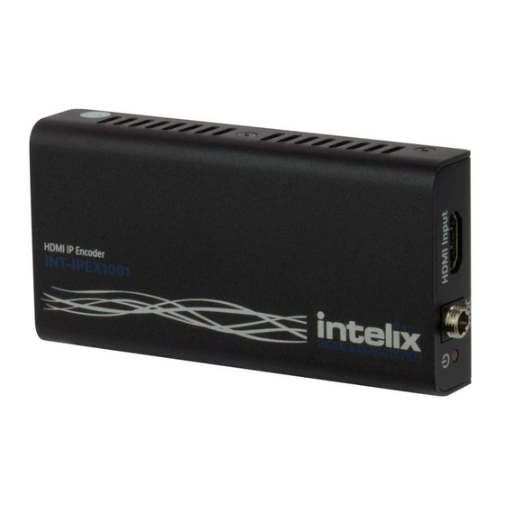
The INT-IPEX1001 is an HDMI video to M-JPEG encoder which broadcasts the
video via multicast packets through the LAN output to the entire network.
The INT-IPEX1001 has a built-in EDID of 1080p/30 with 2 channel audio. The
INT-IPEX1002 receives the multicast packet stream on the LAN input and
decodes the M-JPEG video back to an HDMI formatted video stream.
While the INT-IPEX1000 series extenders use Ethernet switches to distribute a
video signal to multiple displays, these devices must be installed on their own
dedicated network infrastructure.
Important notice:
•
Do not attempt to disassemble or alter the housing. There are no user-serviceable parts
inside the unit. Doing so will void your warranty.
•
To minimize the possibility of equipment damage from electrostatic discharge (ESD), all
source and destination equipment must be powered off during installation.
•
Do not connect the device to a telecommunication outlet wired to unrelated equipment.
Doing so may damage the unit or any connected equipment. Ensure all connected twisted pair
cabling is straight-through (point-to-point).
•
Allow proper ventilation to reduce the risk of thermal failure.
Advertisement
Table of Contents

Related Manuals for Intelix INT-IPEX1001


Summary of Contents for Intelix INT-IPEX1001
- Page 1 The INT-IPEX1001 is an HDMI video to M-JPEG encoder which broadcasts the video via multicast packets through the LAN output to the entire network. The INT-IPEX1001 has a built-in EDID of 1080p/30 with 2 channel audio. The INT-IPEX1002 receives the multicast packet stream on the LAN input and decodes the M-JPEG video back to an HDMI formatted video stream.
- Page 2 INT-IPEX1001 Connections Power LED Power Input HDMI Input LAN Port with Data and Link LEDs Reset Button INT-IPEX1002 Connections LAN Port with Data and Link LEDs Reset Button Power LED Power Input HDMI Output LED States When a connection is detected, the green (left) and amber (right) LEDs on the LAN port will light.
- Page 3 (INT-IPEX1001). If the extenders are connected to a network switch with PoE, such as the INT-IPSW1100 series,power supplies are not required for use. Plug the optional power supplies (PS-5D-10) into the power input port of the extenders and lock the power supply to the power connector by twisting the locking collar clockwise.
-
Page 4: Technical Specifications
Technical Specifications Input/Output Connections LAN port One (1) 8P8C-F HDMI Input (INT-IPEX1001) One (1) HDMI Type A Receptacle HDMI Output (INT-IPEX1002) One (1) HDMI Type A Receptacle 5vDC Input One (1) Threaded Locking Barrel (5.5 mm OD; 2.6 mm ID)
Need help?
Do you have a question about the INT-IPEX1001 and is the answer not in the manual?
Questions and answers