
Subscribe to Our Youtube Channel
Related Manuals for Speco ONSIP OPTZ36XO


Summary of Contents for Speco ONSIP OPTZ36XO
- Page 1 ’ ’ ONSIP OPTZ36XO ONSIP OPTZ36XI Rev.1.0 (Nov., 2011)
-
Page 2: Revision History
’ ’ Revision History Date Rev No. Description 2011-11-01 First manual revision creation. Rev.1.0 (Nov., 2011) - Page 3 ’ ’ Warning & Cautions If you fail to read this information and handle the product incorrectly, faulty or malfunction as well as death or serious injury may occur. This Unit should be installed by train ed personnel. Immediately stop using when the product emits smoke or abnormal heat.
- Page 4 ’ ’ Indications: Warning: Death or Serious Injury will occur without following Warning. Caution : Operational Problem(Faulty & Malfunction) will occur without complying with Caution Reference : Technical Information for Users Rev.1.0 (Nov., 2011)
- Page 5 ’ Table of Contents Table of Contents ................5 1. Introduction ................... 7 1.1. Overview of ONSIP OPTZ36XO/I ..............7 1.2. Specification ................... 8 1.2.1. Basic Specification 1.2.2. Detailed Specification of Camera Module & PTZ오류! 책갈피가 정의되어 있지 않습니다. 1.2.3. Basic Specification오류! 책갈피가 정의되어 있지 않습니다.
-
Page 6: Trouble Shooting
’ ’ 4. Installation .................. 28 4.1. Required System Specification ..............28 4.2. Quick Installation Guide ................29 5. Trouble Shooting ................35 5.1. No Video on Viewer................... 35 5.2. Windows vista and Windows 7 User for Record & Capture Problem ....36 5.3 Technical Inquiry.................. -
Page 7: Introduction
IP Network as well as supports bi-directional audio communication by allowing transmission of audio from Client PC to ONSIP OPTZ36XO/I. ONSIP OPTZ36XO/I, with completed Integration with analog CCTV camera, Digital and network technology, is applicable for various sectors such as Security, Remote Monitoring, Remote Education, Simple Video Conference as well as Internet Broadcasting System etc. - Page 8 Simple Access via Internet explorer Client/Viewer Speco-NVR CMS Software Dynamic IP DDNS support Supported by Speco Technology’s Management Server 802.1x authentication, User ID & Password Protection, IP Security Management Filtering, Audio per user and Bi-directional audio communication configuration control Sync to PC...
- Page 9 ’ ’ Security Surveillance (Building, Stores, Manufacturing Device, Parking Lot, Bank, Public Office & Military etc) Remote Monitoring (Hospital, Kindergarten, Traffic Status, Public Area) Video Conference, Remote Lecture, Internet Broadcasting Climate & Environment Surveillance Rev.1.0 (Nov., 2011)
- Page 10 ’ ’ 2. Production Description Open the package and check if the followings are included; Contents Description Remark Bracket & Housing Outdoor Housing, Wall Mount Bracket Accessories Screw (M4x15 4EA), Safety Cable Manual Housing Installation Manual IP Camera Camera body Wrench, Safety Cable, Cable Tie, Terminal Block Tools &...
- Page 11 ’ ’ CMS Software ONSIP OPTZ36XO/I IP-Installer (Speco-NVR) PC based Client for monitoring/storing Video/Audio Speed Dome Network Camera IP Assignment Program transmitted form Product (Max. 64CH supported) Rev.1.0 (Nov., 2011)
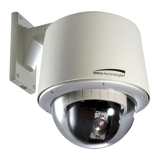
- Page 12 ’ ’ Fig 2-1. External View of ONSIP OPTZ36XO/I & & 12VDC Fig 2-2-1. Terminal Block, LAN & Power Connector Rev.1.0 (Nov., 2011)
- Page 13 ’ ’ Fig 2-2-2. Terminal Block, LAN & Power Connector Rev.1.0 (Nov., 2011)
- Page 14 ’ ’ & & Fig 2-3-1. Connector Part Rev.1.0 (Nov., 2011)
- Page 15 ’ ’ 1. Bubble 9. LAN (100 Base-T) 2. Lock Screw 10. RS-485 (D+, D-) 3. Camera 11. Power Input (DC12V) 4. Dip Switch1 12. Aux 5. Dip Switch2 13. Video out (Analog CVBS) 6. Lock Holder 14. Power LED 7.
-
Page 16: Specification
Connect 12 Volt DC adaptor to this terminal for supplying power to the network camera. AC adapter which is compliant to the specification for ONSIP OPTZ36XO/I should be used. Misuse of power supply can cause damage to ONSIP OPTZ36XO/I. Speco assumes no responsibility for misuse of the power supply. -
Page 17: Onsip Optz36Xo
HEATER/FAN Used for connecting power cable of heater and fan. Power cable of heater and fan is in the bracket. Alarm In/Out (ALARM/AUX) Used for connecting alarm sensor, alarm annunciation device to ONSIP OPTZ36XO/I. Class Description Alarm IN Sensor In (+). - Page 18 ’ ’ Fig 2-5. Relay Connection Diagram (Left: lower than 30V, 2A, Right: Higher than 30V 2A) Alarm Connect external alarm sensor. Examples of sensing devices are infrared sensor, motion sensor, heat/smoke sensor, magnetic sensor, etc. Connect the two wires of the sensors to “SNS In”. The sensor type (NC/NO) can be set in admin page.
- Page 19 ’ ’ 3. Bracket Installation 3.1. ONSIP OPTZ36XO & & 1. Open the Dome Cover by unscrewing with wrench. Rev.1.0 (Nov., 2011)
- Page 20 ’ ’ 2. Configure the DIP Switch by referring Appendix. When using system controller for the control of the dome, always set the RS-485 communication channel to be: 2400 bps, 8 bit, 1 stop bit, no parity. 3. Place the Dome Cover and screw. Rev.1.0 (Nov., 2011)
- Page 21 ’ ’ The wall should be strong enough to hold 4 times of the weight of the camera (5.3 KG). This means that the wall should withstand weight of 21.2 KGs in the minimum. 1. Pass the combined cable through the inside Cable Gland. CABLE GLAND COMBINED CABLE 2.
- Page 22 ’ ’ Hidden Cable Exposed Cable 3. Connect Sun-Visor with Wall Mounting Bracket. (1) 4. After connecting Product and Cable, install the product by inserting Product into internal fixing hole of housing and turning in clockwise. (2) 5. Assemble the Bubble. (3) Rev.1.0 (Nov., 2011)
-
Page 23: Onsip Optz36Xi
’ ’ 3.2 ONSIP OPTZ36XI 1. Open the Dome Cover by unscrewing with wrench. 2. Configure the DIP Switch by referring Appendix. When using system controller for the control of the dome, always set the RS-485 communication channel to be: 2400 bps, 8 bit, 1 stop bit, no parity. Rev.1.0 (Nov., 2011) - Page 24 ’ ’ 3. Place the Dome Cover and screw. Ceiling board should be strong enough to hold the weight of approx.. 2Kg. Rev.1.0 (Nov., 2011)
- Page 25 ’ ’ 1. Prepare 190mm Diameter Hole on the ceiling. 2. Place Safety Wire between suspension and Safety Ire Hole to prevent falling-off. 3. Fold the Lock Lever and insert the bracket into the ceiling hole. 4. Fix the bracket to the ceiling with screws. Rev.1.0 (Nov., 2011)
- Page 26 ’ ’ Prepare 190mm Diameter Hole on the Place Safety Wire between suspension Ceiling. and Safety Wire Hole to prevent falling- off. Fold the Lock Lever and insert the Bracket into the Ceiling Hole. Fix the Bracket to the Ceiling with Screws. 5.
- Page 27 ’ ’ Rev.1.0 (Nov., 2011)
- Page 28 ’ ’ 4. Installation Required Specification of PC for Camera Configuration & Control. Class Recommendation Remark Pentium-4 3Ghz Graphic Card Higher than ATI Chip-Set based 64M 1600x1200(UXGA) LAN Card Higher than 100Mbps Windows XP Web Browser Higher than Internet Explorer 6.0 * Operating Systems supported: Windows 2000 Professional, Windows XP / Vista / 7 Rev.1.0 (Nov., 2011)
-
Page 29: Onsip Optz36Xo
Power will be applied to product separately via Power Device (AC Adaptor). 2. Install Speco-NVR Speco-NVR is a multi-channel CMS program for to IP camera or Video server. Install Speco-NVR on remote PC to connect to these products. It is needed to assign connection information to Speco-NVR program before connection. - Page 30 ’ ’ Admin Page Button IP installer Figure 4-2. Speco-NVR Follow the sequence below for setting the IP parameter Run IP installer ① in IP installer window.> Double click on ② > Fill in ④ > make a selection in ⑤ > Fill the Click parameters in ⑥...
- Page 31 ’ ’ Click on the field in ③ for sorting and rearranging the list. Select network mode that best suits from the drop down list in ⑤. You can choose either Static or ADSL and Auto (DHCP), respectively. If ADSL and Auto are selected, the fields in ⑥ is deactivated.
- Page 32 For the use of Web Viewer, Active-X module should be installed. If internet access is available, you can download it by accessing Camera or if you install Speco-NVR, Active-X module will be installed together. Connection to Admin Page Basic Control Buttons Video Crop Control Fig 4-3.
- Page 33 SAVE button. You can see the live video when you click the live view button as below. When you exit Speco-NVR, you have to input the ID/PW, admin/1234. Details for the Speco-NVR can be found in [Speco-NVR User’s Guide].
- Page 34 4. Initial Configuration by connecting Admin Mode All Parameters of ONSIP OPTZ36XO/I are initially set as factory default. So you must change them with appropriate value to your network configuration by accessing via Admin Tool. Admin Tool Access Method is as below.
-
Page 35: Trouble Shooting
’ ’ 5. Trouble Shooting Network Connection Status Check(Ping Test) You can check the Network Connection Status by doing Ping Test. - Start > Run > cmd > Ping IP Address (EX>ping 172.16.42.51). - If you get the response such as “Reply from~”, Network Configuration & Connection Status is good. Please re-try to access or refer to other trouble shooting category. - Page 36 & & For the use of Video Recording & Capture function on Speco-NVR and Web Viewer, Windows Vista and Windows 7 Users are required to configure “User Account Configuration” and “Program Execution Entitlement Configuration”. If not configure, Recorded File won’t be generated or Captured Image on Web Viewer won’t be saved.
- Page 37 ’ ’ Windows 7 Configuration 1. User Account Configuration 1) Select “User Account” on Control Panel 2) Select “Change User Account Control Setting” 3) Set the Alarm Level at the lowest “Never Notify” Rev.1.0 (Nov., 2011)
- Page 38 ’ ’ 2. Program Execution Entitlement Configuration 1) Select “NVR” icon on the wallpaper 2) Select “Properties” menu popped up by clicking right button on Mouse 3) Select Check Box of “Run this program as an administrator” from the compatibility Tap. Rev.1.0 (Nov., 2011)
- Page 39 ’ ’ Please contact to your supplier if you still have problem even taking all trouble shootings. For the quickest solution, please prepare all information below; 1. Product Model Name 2. Serial No. & Mac Address 3. Date of Purchase 4.
-
Page 40: Appendix
At ONSIP OPTZ36XO/I, FAN & Heater will operate. Cablings for the Fan & Heater are completed in the Factory At ONSIP OPTZ36XO/I, FAN & Heater will operate by connecting power cable of FAN & Heater to HEATER/FAN connector at bottom of product. . Detailed Specification... - Page 41 ’ ’ Weight 3.4kg (including Camera : 5.3kg) Rev.1.0 (Nov., 2011)
-
Page 42: Dip Switch Setting
’ ’ 6.2. DIP Switch Setting A. ID Configuration * Factory Default: Camera ID = 1 (1-ON, 0-OFF) DIP SW ID VALUE DIP SW ID VALUE DIP SW ID VALUE 10000000 00010100 11110010 01000000 10010100 00001010 11000000 01010100 10001010 00100000 11010100 01001010 10100000... - Page 43 ’ ’ 01101000 10111100 00100110 11101000 01111100 10100110 00011000 11111100 01100110 10011000 00000010 11100110 01011000 10000010 00010110 11011000 01000010 10010110 00111000 11000010 01010110 10111000 00100010 11010110 01111000 10100010 00110110 11111000 01100010 10110110 00000100 11100010 01110110 10000100 00010010 11110110 01000100 10010010 00001110 11000100 01010010...
- Page 44 ’ ’ 11100001 10101101 11000111 00010001 01101101 00100111 10010001 11101101 10100111 01010001 00011101 01100111 11010001 10011101 11100111 00110001 01011101 00010111 10110001 11011101 10010111 01110001 00111101 01010111 11110001 10111101 11010111 00001001 01111101 00110111 10001001 11111101 10110111 01001001 00000011 01110111 11001001 10000011 11110111 00101001 01000011...
- Page 45 ’ ’ B. PROTOCOL Set by 3 Switch of DIP Switch 2. Factory Default: Pelco-D & Pelco-P (Auto) DIP SW2 - 3 OFF / OFF Pelco-D or Pelco-P ON / ON Maxpro protocol C. BAUD RATE SETTING Set by 7 Switch of DIP Switch 2.
Need help?
Do you have a question about the ONSIP OPTZ36XO and is the answer not in the manual?
Questions and answers