Table of Contents
Advertisement
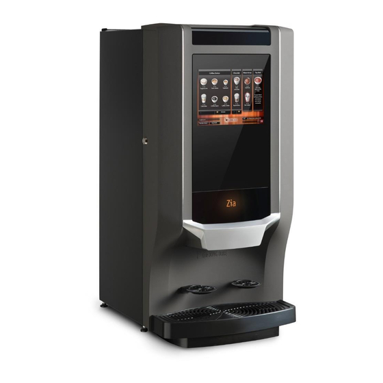
Zia 6000 and 8000
Technical manual
The manufacturer of the machine is:
De Jong Duke
Postbus 190
3360 AD SLIEDRECHT
The Netherlands
Telephone +31 (0) 184 496767
Fax:
+31 (0) 184 416059
series
Model: Zia 6000 and Zia 8000
Machine type: 9CND...
Revision 1.0, English
Reference: 5DTCNP20
www.dejongduke.nl
support@dejongduke.nl
Advertisement
Table of Contents

Related Manuals for de Jong Duke Zia 6000 series


Summary of Contents for de Jong Duke Zia 6000 series
- Page 1 Technical manual Model: Zia 6000 and Zia 8000 Machine type: 9CND… Revision 1.0, English Reference: 5DTCNP20 The manufacturer of the machine is: De Jong Duke Postbus 190 3360 AD SLIEDRECHT The Netherlands Telephone +31 (0) 184 496767 www.dejongduke.nl Fax: +31 (0) 184 416059 support@dejongduke.nl...
- Page 2 No liability is accepted for the consequences arising from operation of the equipment in accordance with the information contained in these instructions. J.M. de Jong Duke automatenfabriek b.v. reserves the right to alter specifications at any time and without prior notification to the purchaser.
-
Page 3: Table Of Contents
CONTENTS SAFETY ....................6 ..................6 AFE USE ..................6 AFETY RISKS ..................6 NSTALLATION ..................6 AINTENANCE ................7 XTENDED DOWN TIME DESCRIPTION OF THE MACHINE ............8 ................... 8 ENERAL ..............8 HE FRONT OF THE MACHINE ............8 VERVIEW OF THE MACHINE INTERIOR .............. - Page 4 ................... 23 OILER .......... 26 OSITION OF VALVES IN THE HOT WATER SYSTEM ..............28 WAY VALVE OUTLET VALVE 5.10 3- ............... 29 WAY VALVE BREWER VALVE 5.11 P ............... 30 RESSURE VALVE 5.12 S ............30 AFETY PRESSURE VALVE ®...
- Page 5 ..................69 UP SENSOR ..................69 ANGUAGE ................70 AYMENT SETTINGS ..............71 OFTWARE CONFIGURATIONS 7.10 L ................72 OAD PERMISSIONS 7.11 C ................ 73 LOCK TIME SETTINGS 7.12 J ................... 74 UG SETTINGS 7.13 I ..................75 MAGES 7.14 T ..................
-
Page 6: Safety
Safety Safe use Before using your coffee machine, please read the safety instructions and all of the information in this manual first and keep it for future reference. Be careful! This machine serves hot drinks. Don’t reach beneath the dispensing nozzles and hot water spout after selection and during dispensing. -
Page 7: Extended Down Time
The appliance shall not be cleaned by a water jet. Do not use water in or near the machine unless the instructions explicitly give direction to do so. Do not use aggressive cleaning products or abrasives to clean (parts of) the machine. -
Page 8: Description Of The Machine
Description of the machine General The machine is a compact semi-automatic machine for the preparation and vending of hot and optional cold drinks. The front of the machine The machine can be operated by using the touch panel on the door. By touching one of the selection images on the screen, a product choice can be made. -
Page 9: Backside Of The Machine
Backside of the machine 1 Water connection 2 Holes for water filter in base cabinet. (optional) 3 Fan 4 Power cord... -
Page 10: Options And Accessories
Options and accessories The machine can be extended with several options. Some options can interference or exclude other options. Base cabinet Part number 9OKNK1140 is a base cabinet with condimental trays. Part number 9OKNK1110 is a base cabinet with closed front. Dimensions base cabinet: Height: 850 mm / 33.5 inch... -
Page 11: Cold Water Unit In Base Cabinet
Cold water unit in base cabinet A cold water unit for chilled water or a unit for carbonated and chilled water can be installed in the base cabinet. Part number 9VKS019 chiller for chilled water. Part number 9VKS017 chiller for chilled and carbonated water. -
Page 12: Payment Systems
Payment systems A Coin validator in a side unit. A coin validator/acceptor communicating via the MDB protocol can be connected to the control board. B Change giver in a side unit. A coin change giver, communicating via the MDB protocol, can be connected to the control board. -
Page 13: Technical Data
Technical data Type plate The type plate is mounted at the inside of the machine, at the top left. The type plate shows: Manufacturer Serial number Type/model specification Power connection Date of production Water connection Technical specifications Dimensions: Width 360 mm / 14.2 inch Depth 510 mm / 20.1 inch Height : Standard machine:... -
Page 14: Dimensions Of The Machine
Dimensions of the machine The machine can be extended with several options. In the pictures below are the dimensions for a standard sized machine. Front view 170mm 6.7 inch 360mm 14.2 inch Top view 80mm 3.2 inch 350mm 13.8 inch door 160mm Door lock... -
Page 15: Water Specifications
Water specifications Water line pressure: See chapter 4.2 The water flow rate from the mains should be minimal 2,5 liter per minute. For an optimal operating of the coffee machine and an optimal coffee quality, the water should be conform the following specifications: - Hardness: 6-8 ºdH (German hardness) or11-14 °fH (French hardness) - pH value: Minimal 6.5... -
Page 16: Function Of The Components
Function of the components In the next paragraphs you find a detailed description of the several parts and components in the machine. Understanding of the function of the different components is essential for maintaining the machines. Hot water system The water system is positioned at the back side of the machine and accessible from the back. -
Page 17: Schematic Diagram Of The Water System
Schematic diagram of the water system (standard 9CND machine, 2 mixers) Mains water supply Inlet valve Pressure reducer 0,9 bar Flow meter Pump 2 Pump 1 Temperature and level Boiler with sensor heater 2-way outlet valve 3-way outlet valve Mixer Mixer water Boiler 1... -
Page 18: Inlet Valve
Inlet valve The inlet valve is controlled by the level sensor in the boiler and is switched on during a dispense of hot water to the brewer or mixer. The inlet valve is a 24V DC valve. The inlet valve contains a backflow protection. This backflow protection is preventing that water is flowing back into the water supply. - Page 19 Procedure to adjust the pressure reducer: 1. Remove the lower back plate from the machine. 2. Remove the tube clamp and stop. (see picture) 3. Connect the manometer to the tube. 4. Pull out the knob to unlock the reducer. 5.
-
Page 20: Water Flow Meter/Water Counter
Water flow meter/water counter The water flow meter measures the quantity of the water flowing through the hot water pressure system. Three functions are based on the water flow meter: 1. The water dosages for the consumptions are based on quantity of the pulses generated by the flow meter. -
Page 21: Pump
Pump The pumps are generating the pressure and flow of the water. The pumps increase the pressure to the required brewing pressure (1.5 till 10 bar). The pump is a vibration pump. The plunger vibrates up and down, therewith a pressure can be build-up. - Page 22 - The B2C espresso machine has 2 pumps, parallel connected and can brew espresso on 8-10 Bar or coffee on a low pressure 1-4 bar. The variation in pressure generates an excellent coffee or espresso flavor. 2 pumps system (Zia 8000 series) 1 pump system (Zia 6000 series) Part number pump: 4EMT027...
-
Page 23: Boiler
Boiler The hot water is prepared in the boilers. The machine is equipped with two boilers, made out of stainless steel. The boilers are connected in serial; water from boiler 1 flows into boiler 2 and from boiler 2 through outlet valves out of the hot water system. The water inlet is in the bottom of the boiler, the outlet at the top. - Page 24 Electrical boiler connections: Temp. Temp. Triac on safety safety heater 230VAC or 110VAC Connections boiler 1 number Wire color function Green-Purple Temperature common Pink Temperature Dark-red /Black Level detection Black Heater phase Blue Heater neutral Black Temperature safety Brown Temperature safety Yellow/grey Earth boiler housing Connections boiler 2...
- Page 25 Temperature safety / clixon: The temperature safety switch is positioned on the side of the boiler. In the housing is a bi-metal disk which switch if the device gets too hot. This safety protects the heater against overheating if the control system does not switch off the heater.
-
Page 26: Position Of Valves In The Hot Water System
Level: The level in the boiler is detected by the stainless steel housing of the sensor. The boiler is connected to ground. On the housing is a positive signal from the control system. If the sensor is in the water, current is able to pass through the water. The control system is detecting the water level because of this current. - Page 27 2-bar pressure 12-bar pressure valve safety valve Hot water valve 3-way coffee valve 2-way outlet valve The two way hot water outlet valve is equipped with a special disc between valve and hose nozzle. This disc has a very small hole (0.7mm) in the middle. All the water must flow through this very small hole, causing the air in the water to dissolve.
-
Page 28: 2-Way Valve / Outlet Valve
2-way valve / outlet valve The two way valve is the outlet from the hot water system to a component. The moveable plunger has an integral seat which, when the solenoid coil is energized, moves off the valve (direct operated) orifice opening the valve. When the coil is de-energized, a return spring repositions the plunger in the original closing position on the valve, thus cutting off the flow of the fluid. -
Page 29: 3-Way Valve / Brewer Valve
5.10 3-way valve / brewer valve ® The three way valve is the outlet from the hot water system to the CoEx Brewer (coffee valve) and has a channel from the brewer into the drip tray. Herewith the coffee residue can flow back from the brewer into the waste bucket. The function of the valve is based on a spring together with the system pressure which is pressing the plunger on the valve-seat. -
Page 30: Pressure Valve 2 Bar
5.11 Pressure valve 2 bar The 2 bar pressure valve is a mechanical pressure valve. This valve automatic opens if 2 bar pressure is reached. This pressure valve can be switched off electronically by the 2-way expansion valve, in front of this 2 bar valve. The 2-way expansion valve is switched off during a vend cycle. -
Page 31: Coex ® Brewing System
® 5.13 CoEx brewing system The combined coffee and espresso brewer. The brewer is one of the most important parts in the machine. The quality of the coffee depends very much on the condition of the brewer. It is very important to keep the unit clean, also for a good functionality. -
Page 32: Removal Of The Coex Brewer
® 5.14 Removal of the CoEx brewer Removal of the brewer is necessary for performing maintenance. Carry out the following procedure for removal of the brewer: Open the door of the machine. Remove the outlet tube from the brewer. Push the green handle upwards and pull the brewer out off the machine at the same time. -
Page 33: Install The Brewer
5.15 Install the brewer Carry out the following procedure to replace the brewer: Place the brewer in the bracket. Push the brewer firmly in the machine till you hear “click” and the green handle is turned downwards in its home position. Make sure that the green handle is in the down position. -
Page 34: Brewer Cycle
5.16 Brewer cycle Home position / Start position After dosing the coffee the brewer start running. The motor runs clockwise till closed position. Closed position The dosed coffee is pressed together between the upper and lower piston. After pressing the coffee together the water is dosed through the piston, into the coffee cake and flows through the filter screen out into the top and outlet of the brewer. - Page 35 Back to home After swiping the coffee cake away, the brewer runs in the clock wise direction to the home position. Start/home position The brewer is ready for a new cycle.
-
Page 36: Brewer Motor And Micro Switch
5.17 Brewer motor and micro switch The brewer motor and micro switch are mounted on a bracket. Specifications brewer motor: 24Vdc. No load: Speed 32 rpm, 0,10 A ± 0,05A Normal load: speed 25 rpm, 0,45A, 1,5 Nm. Stall: 1,8A ± 10%. The motor is controlled in two directions, clockwise and counter clockwise. -
Page 37: Upper Piston
5.18 Upper piston ® The upper piston is mounted in the top of the CoEx brewer. This upper piston is removable with the fixation knob on the top of the brewer. To remove: Turn the knob clockwise To fit on brewer: First place the complete upper piston in the right position, then turn the know counter clockwise. -
Page 38: Controlling Coffee/Espresso Pressure Switch
5.19 Controlling coffee/espresso pressure switch ® With the unique patented system the CoEx -brewer can make Coffee and espresso consumptions in one brewing system. The pressure for coffee and espresso is different, coffee is made with 3 - 4 bar pressure, espresso with 9 bar pressure. - Page 39 Coffee cycle: When coffee is chosen, the start flow is relative low and will not activate the pressure switch. (Spring is strong enough to keep pressure switch in coffee position) The coffee passes the primary restriction and can then flow through the large coffee channel. Espresso cycle: When espresso is chosen, at first the flow is high and will activate the pressure switch.
-
Page 40: Seals
5.20 Seals The brewer contains two pistons, the upper piston and lower piston. There are three sealing responsible for the sealing of the pressure room: Two in the lower piston and one in the upper piston. Hot water enters the cylinder (through the lower piston) between the two sealing rings in the piston. -
Page 41: Replace Seals In Lower Piston
5.21 Replace seals in lower piston 1. Needed tool: Screw driver 2. Unscrew the bolt in top of the brewer and loosen the two other bolts 2 turns. remove Loosen 2 turns 3. Remove waste wiper. 4. Push left and right housing sideward an pull the cylinder with piston out of the brewer. -
Page 42: Mixer
5.22 Mixer The mixer consists of a mixer motor, to which a mixer blade and a mixer house are connected. The mixer is controlled by the control board and ensures a correct mixing of the ingredients and the water. Furthermore, the mixer whips air in de consumptions and forms a crème layer. - Page 43 Disassembling the mixing system: 1. Remove outlet pipes from the ingredient canisters. 2. Turn the bayonet catch counter clockwise (approx. 10º). 3. Remove the mixer house by pulling it towards you. 5. Pull the mixer blade towards you.
- Page 44 6. Turn the base plate further counterclockwise and pull it towards you. 7. Ready Assembling the mixing system: 1. Install the base plate. 2. Install the mixer blade. Be sure that the arrow on the blade is at the flat side of the shaft.
- Page 45 3. Install the mixer house. 4. Turn the bayonet catch clockwise. 5. Install the outlet pipes on the ingredient canisters. 6. Ready.
-
Page 46: Grinder
5.23 Grinder The grinder can been build in the door or on the base plate next to the other ingredient canisters. In the grinder the coffee beans are ground through two metal blades to fine ground coffee. These two blades in the grinder are mounted horizontally. The upper blade in the grinder is a fixed blade and the lower blade is rotating, driven by a motor of 24VDC. -
Page 47: Grinder In Door
5.24 Grinder in door The grinder is mounted in a housing fixed with hinges in the cabinet. By opening the door the grinder will rotate automatically and stay in the door. The grinder can be moved above the brewer for making a test drink with coffee from the grinder. -
Page 48: Grinding Adjustment
5.26 Grinding adjustment. For the adjustment of the grinder you can adjust the grinder blades inside the machine without disassembling the grinder. The machine will give a finer grinding by turning the screw counter clockwise and a coarse grained coffee by turning the knob clockwise. -
Page 49: Default Grinder Setting
5.27 Default grinder setting The grinder is default set as described below: Remove the upper part of the grinder from the machine by pulling it upwards. Remove the black adjustment worm- wheel by pulling the 2 pins outwards (1) and at the same time lifting this wheel upwards. -
Page 50: Ingredient Canisters
Replace the black adjusting worm-wheel Replace the grinder back in the black housing. Test the result by taking consumptions. Fine adjustments can be done by rotating the adjusting worm-wheel. (see chapter 5.26, grinding adjustment.) 5.28 Ingredient canisters The canisters can have a metal auger or plastic auger. -
Page 51: Electronic Hardware
Electronic hardware Hardware MoVeC ICEQ (Modular Vending Controller for Intelligent Connected Equipment) The electrical system consists of the following main components: Power supply board IO board Control board Display board with touch screen Power supply Inside machine IO board Speaker Control board USB stick Cup sensor... -
Page 52: Power Supply
Power supply The power supply is located at the back plate of the machine behind the ingredient canisters. The mains voltage is connected to the power supply board. For over voltage protection, the power supply has been equipped with a fuse. The heating elements are directly connected to the mains, via the On/off switch and the IO board. -
Page 53: Control Board
Control board The control board is located at the inside of the door. The control board controls the operation of various components. The signals are send to the IO board. On the control board you also find the connections for other PCB’s and payment systems. -
Page 54: I/Oboard
I/O board The IO board is controlled by the control board. The I/O board controls the mechanical components such as dosing motors, boiler(s), brewer motor, mixers and valves. Part number: 5EPR132, 27 outputs and 2 heater outputs J4, J3 J2, J1 J1,J2 Switching wires heater 1 J3,J4 Switching wires heater 2 24Vdc input... -
Page 55: Connectors On The Io Board
Connectors on the IO board Connector Component Wiring color Heating element 1 Blue Heating element 1 Blue Heating element 2 Blue/white Heating element 2 Blue/white J5-1 +24V DC supply J5-2 +24V DC supply J5-3 Black J5-4 Black J8-1 +24VDC (common) Orange J8-2 Valve brew/mix 1... - Page 56 J9-1 +24V DC (common) Orange J9-2 Ingredient motor 1 coffee or grinder Purple J9-3 Ingredient motor 2 coffee or grinder Brown/Red J9-4 Brewer motor + Gray/White J9-5 Brewer motor - Gray J9-6 Brewer micro Gray/Black J9-7 Paper switch Empty J9-8 Common sensors Green/Purple J9-9...
-
Page 57: Lvds Display And Touch Screen
LVDS Display and touch screen. Part numbers: Display LVDS: 4EPR022 Touch screen: 6CSS053 Control board: 5EPR140 PCT controller: 4EPR023 PCT controller 4EPR023 Speaker Part number: 4ELP001... -
Page 58: Cup Sensor
Cup sensor The cup sensor sense a cup on the cup stand. Maximum two cup sensors can be connected in the machine. One for the right outlet and one for the center outlet. A cup must be placed on the correct position on the cup stand before the start button is green and the cycle can start. -
Page 59: Electrical Schematics
Electrical schematics Electrical Diagram - MoVeC ICEQ - 9CND: 230Vac Electrical Diagram - MoVeC ICEQ – Controller board - Zia... - Page 60 Electrical Diagram - MoVeC ICEQ - 9CND: IOB connector J6 Electrical Diagram - MoVeC ICEQ - 9CND: IOB connector J8, J9 en J10...
-
Page 61: Service And Programming
Electrical Diagram - MoVeC ICEQ - 9CND: IOB connector J9 Service and programming Mode without password After opening the door the service mode is shown in the screen. This screen gives the options: - Rinse (grey in picture) - Weekly cleaning cycle brewer - Show product counters - Software information Only buttons in light green color work. -
Page 62: Functions Without Password
• Possible moving parts inside the machine, beware of trapped fingers if the service key is placed when the door is open. • Beware of hot parts and hot liquid inside the machine, even after the power is disconnected. Functions without password Inserting of the safety key makes the rinse functions available for use. - Page 63 Software information This screen shows all types of software and hardware information about the machine.
-
Page 64: Service Mode With Password Access
Service mode with password access After opening the door the first level service screen is shown. Press the login button right at the top, a new screen as shown here will pop up. Enter the technician password and then press the login button left under. -
Page 65: Recipe Settings
Recipe settings - Water/ingredient settings. The water and ingredient dosage and other timings can be adjusted per available recipe. (see chapter 7.4.2 and 7.4.3 for detailed explanation) - Strength control %. The max strength difference from the medium dosage can be set. The medium dosage is the set dosage in the recipe settings of each individual consumption. - Page 66 7.4.2 EXAMPLE: (Fresh brew) Coffee recipe in a bean to cup machine Coffee = The settings for the ingredient fresh brew coffee. Press coffee, this gives a new screen: Delay = 0.0 means: Coffee is immediately dosed in the brewer, no delay. Duration = 2.5 means: The auger in the coffee canister rotates for 2.5 seconds, giving a certain amount of coffee in the brewer.
- Page 67 7.4.3 EXAMPLE: Cappuccino recipe in a bean to cup machine Beans = the duration time the grinder grinds beans. 3.0 means a duration of 3 seconds for the grinder. Subr topping = the recipe for topping in the cappuccino. - 1. Topping 0.5 in the first column means a delay of 0.5 (so first there is water in the mixing bowl) 1.0 in the second column means a duration of 1.0...
-
Page 68: Boiler Temperature
7.4.4 Sub product milk and sugar The sub products milk and sugar have their own water and product settings. In this example: Delay = delay start dispensing product after start recipe = 0,5 sec. Duration = duration auger rotates, dispensing product = 0,7 sec. -
Page 69: Cup Sensor
Cup sensor Show cup sensor signal: The signal of both sensors can be read individually. This way the visibility of a cup can be tested also. Cup sensor setting: The sensitivity of the cup sensor is adjustable. The value can be adjusted between 0 and 4000. The value 0 means switched off. -
Page 70: Payment Settings
Payment settings With the payment settings menu the product prices and the functions of the payment system can be set. Ln l - Consumption prices: To adjust the price for all available consumptions. For each individual consumption type, 2 prices are available: Pricelist 1 and pricelist 2. -
Page 71: Software Configurations
Software configurations select active configuration: Select the configuration file with which the machine have to work. The configuration file which is currently active is in grey color, all other inactive files are in green. Delete configuration: Delete a configuration file. Backup configuration: This makes a copy of the active configuration with all settings. -
Page 72: Load Permissions
7.10 Load permissions In this menu the permissions, e.g. to show images on the screen of the machine, can be loaded from an USB stick, It is possible to explore the maps on the stick to find the needed permission file. If the coffee machine is not configured for images, the standby images and distributing images option can be enabled on the DJD coffee machine using the following procedure. -
Page 73: Clock/Time Settings
7.11 Clock/time settings - Screen saver (delay) time This is a delay time in minutes after the last consumption. After this delay, the standby image will appear. If the time is set to 0, the standby image(s) will never show-up in the screen. - Set correct time The actual date and time can be set in this menu. -
Page 74: Jug Settings
Machine off: The machine is switched off during the set time. The display is completely black. The elements are switched off. During this time the machine can only be activated in the service mode. Setting the times in the scheduler: The scheduler has a start time for hour, minute and day. -
Page 75: Images
7.13 Images Logo = A customer specific logo, visible in the user screen. Standby = an image, visible while the machine is not used. Also called screensaver. Distributing = an image, shown during dispense of a consumption. Images needs to have the following file format: .png .jpg... -
Page 76: Test Outputs
- Delete standby images Delete a standby image. - Load distributing images A distributing image can be loaded via an USB stick or via “connect me”. Every individual image can be connected to all consumptions (General) or to individual consumptions. - Select active distributing images One or several image(s) can be selected, if more then 1 is available. -
Page 77: Error Settings
7.16 Error settings This menu contains information and settings for the available warnings and errors. Warning = message on display only. Error = Message on display, machine (partly) out of order - Change error conditions. The condition when a warning or error occurs can be adjusted with this function. -
Page 78: Water Filter Settings
- Reset cleaning error After pressing this button, the machine beeps, and the brewer cleaning message is cleared from the screen. Be sure the brewer is clean, and no cleaning agent or cleaning powder is left in the brewer. 7.17 Water filter settings - No water filter installed. -
Page 79: Show Eva-Dts
7.22 Show EVA-DTS The available EVA DTS information: Element name ID100 Machine Identification ID101 Machine Serial Number ID102 Machine Model Number ID103 Machine Build Standard (operating system number) ID500 System Date / Time Report ID501 System Date ID502 System Time DA100 Debit Card System Identification DA101... - Page 80 CA1000 Manual Cash Filling Summary CA1001 Value Of Cash Filled Since Last Reset CA1002 Value Of Cash Filled Since Initialization CA1500 Value of Tube Contents CA1501 Value of all coins stored in all tubes of the change giver TA200 Token Sales Summary TA201 Value of Vend Token Sales Since Initialization TA202...
-
Page 81: Change The Serial Number
7.23 Change the serial number The machine serial number must be entered here. The serial number of the machine is printed on the CE type plate of the machine. The serial number is used if you use the EVA- DTS function to readout data from the machine and for “connect me”... -
Page 82: Empty Boiler
7.25 Empty boiler Take care, possible hot water comes out of the boilers. In case the machine needs to be stored for a longer time, or needs to be transported (freezing weather, plane) the internal hoses and boilers needs to be emptied. The boilers are emptied due to gravity. -
Page 83: How To Do
How to do How to load a new configuration file from an USB stick? The MoVeC files have the extension .mvq 1. Copy the new file to a USB stick. Example files on USB: 2. Insert the USB stick in the USB port of the machine. (inside the door) 3. -
Page 84: How To Load A New Flash(Swf) Or Movec Iceq File From Usb
How to load a new flash(SWF) or MoVec ICEQ file from USB Upload the MoVeC ICEQ Linux and swf software to the machine: 1. Copy the new files to a USB stick. The files must be placed in the root directory. -
Page 85: How To Get And Load A Permission Key
How to get and load a permission key Collecting coffee machine information: Open the front door of the machine. The service menu is shown on the screen. Select “Software information” button on the touchscreen. Software information screen is shown. Check if the correct software versions are installed: - MoVeC ICEQ version :3.40 or higher - Version flash file... - Page 86 Load the Permissions: Follow the procedure below to load and activate the permission key on the DJD coffee machine(s). Connect a USB memory stick to a working Copy the received “Key.mpf” file to the USB memory stick: Place the Key.mpf file directly in the root directory of the USB stick for ease of uploading.
- Page 87 Load the Permissions: Select the “PgDwn” or “PgUp” button until the button “load permissions” appears. Select the “load permissions” button. Select the “device 0” button. (device0 = USB Memory stick inside door) Select the file “xxx_key_xx.mpf” button. (May need to browse based on saved location of key file.) The file is loaded.
- Page 88 Load the Permissions: Close the door and select the “close door and press here to quit service” button to exit the service menu. The coffee machine starts up again. When the normal operation screen is displayed, the coffee machine is ready for normal use.
-
Page 89: Warning, Failure And Error Messages
Warning, failure and error messages Brewer not in home position The micro switch did not detect the brewer home position on the required moment. Check if the brewer is installed correctly. Remove and replace the brewer following the procedure. Check if the micro leveler is bend. Check if the motor shaft is broken. - Page 90 Filling boiler 1/2 Open and close the machine door for restart, wait until boiler is filled. If message continues: Check if main water is connected and available. Check if inlet valve and pumps works. Check water system in machine Grinder 1/2 blocked A too high current is detected on the output for the grinder.
- Page 91 Startup problem The amount of pulses for the water flow meter during start-up is not reached in time. Open and close the machine door for restart. If message shows again, check the expansion valve, 2 bar valve, pumps, water inlet from mains and inlet valve. Check water flow meter.
- Page 92 Notes: ------------------------------------------------------------------------------------------- ------------------------------------------------------------------------------------------- ------------------------------------------------------------------------------------------- ------------------------------------------------------------------------------------------- ------------------------------------------------------------------------------------------- ------------------------------------------------------------------------------------------- ------------------------------------------------------------------------------------------- ------------------------------------------------------------------------------------------- ------------------------------------------------------------------------------------------- ------------------------------------------------------------------------------------------- ------------------------------------------------------------------------------------------- ------------------------------------------------------------------------------------------- ------------------------------------------------------------------------------------------- ------------------------------------------------------------------------------------------- ------------------------------------------------------------------------------------------- ------------------------------------------------------------------------------------------- -------------------------------------------------------------------------------------------...
- Page 93 Notes: ------------------------------------------------------------------------------------------- ------------------------------------------------------------------------------------------- ------------------------------------------------------------------------------------------- ------------------------------------------------------------------------------------------- ------------------------------------------------------------------------------------------- ------------------------------------------------------------------------------------------- ------------------------------------------------------------------------------------------- ------------------------------------------------------------------------------------------- ------------------------------------------------------------------------------------------- ------------------------------------------------------------------------------------------- ------------------------------------------------------------------------------------------- ------------------------------------------------------------------------------------------- ------------------------------------------------------------------------------------------- ------------------------------------------------------------------------------------------- ------------------------------------------------------------------------------------------- ------------------------------------------------------------------------------------------- -------------------------------------------------------------------------------------------...
Need help?
Do you have a question about the Zia 6000 series and is the answer not in the manual?
Questions and answers