Rockwell Automation SmartGuard 600 Installation Instructions Manual
Hide thumbs
Also See for SmartGuard 600:
- User information (8 pages) ,
- Safety application example (14 pages)

Related Manuals for Rockwell Automation SmartGuard 600


Summary of Contents for Rockwell Automation SmartGuard 600
-
Page 1: Table Of Contents
Topic Page Important User Information North American Hazardous Location Approval General Safety Information About the SmartGuard 600 Controller Before You Begin Set the Node Address Setting the Communication Rate Set the IP Address for Ethernet Communication Install the SmartGuard 600 Controller... -
Page 2: Important User Information
In no event will Rockwell Automation, Inc. be responsible or liable for indirect or consequential damages resulting from the use or application of this equipment. -
Page 3: North American Hazardous Location Approval
SmartGuard 600 Controllers North American Hazardous Location Approval The following information applies when operating Informations sur l’utilisation de cet équipement en this equipment in hazardous locations. environnements dangereux. Products marked "CL I, DIV 2, GP A, B, C, D" are suitable for use in Les produits marqués "CL I, DIV 2, GP A, B, C, D"... - Page 4 SmartGuard 600 Controllers Environment and Enclosure ATTENTION This equipment is intended for use in Pollution Degree 2 Industrial environment, in Overvoltage Category II applications (as defined in IEC publication 60664-1), at altitudes up to 2000 m (6562 ft) without derating.
-
Page 5: About The Smartguard 600 Controller
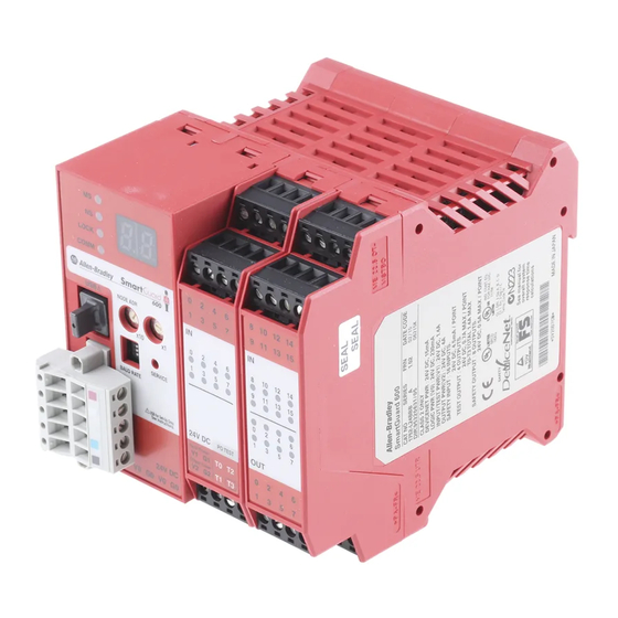
USB and DeviceNet safety communication. In addition, the 1752-L24BBBE controller offers EtherNet/IP connectivity. SmartGuard 600 controllers are certified for use in safety applications up to and including Safety Integrity Level (SIL) 3, according to IEC 61508, Performance Level PL(e) according to ISO 13849-1, and Category (CAT) 4, according to EN 954-1. - Page 6 SmartGuard 600 Controllers 1752-L24BBB Controller Number Feature Module status indicators Alphanumeric display Node address switches Baud rate switches USB port DeviceNet communication connector Terminal connectors Input status indicators Output status indicators Service switch 1752-L24BBBE Controller Number Feature Module status indicators...
-
Page 7: Before You Begin
SmartGuard 600 Controllers Before You Begin Before you install the controller, set its DeviceNet node address and communication rate. Turn off power to the controller before setting the node address or communication rate IMPORTANT via the switches. Do not change the switch settings while the power supply is on. The controller will detect this as a change in the configuration and will switch to the ABORT mode. -
Page 8: Set The Ip Address For Ethernet Communication
You can use any commercially available BOOTP server. If you do not have BOOTP Server capabilities on your network, download the free Rockwell Automation BOOTP server from http://www.ab.com/networks/bootp.html. To set the IP address by using the Rockwell Automation BOOTP utility, follow these steps. 1. Run the BOOTP utility. -
Page 9: Install The Smartguard 600 Controller
For detailed information on EtherNet/IP communication, refer to the EtherNet/IP Performance and Application Solution, publication ENET-AP001. Install the SmartGuard 600 Controller To install the SmartGuard 600 controller, you must mount it on the DIN rail, wire the terminals, and make communication connections. Mount the SmartGuard 600 Controller... -
Page 10: Grounding The Smartguard 600 Controller
The 1752-L24BBB controller has one latch and the 1752-L24BBBE controller has two latches on the bottom of the controller. Grounding the SmartGuard 600 Controller This product is grounded through the DIN rail to chassis ground. Use zinc plated ATTENTION yellow-chromate steel DIN rail to assure proper grounding. -
Page 11: Connecting A Power Supply
Class 2 circuits or limited voltage/current circuits defined in UL 508. The following Rockwell Automation 1606 power supplies are Class 2, SELV- and PELV-compliant, and they meet the isolation and output hold-off time requirements of the SmartGuard 600 controller: •1606-XLP30E... -
Page 12: Wiring The Smartguard 600 Controller
SmartGuard 600 Controllers Power Supply Connections Wiring the SmartGuard 600 Controller page 24 for appropriate wire size and torque specifications. Controller Terminal Descriptions Terminal Designation Description Power terminal for internal circuit (logic). Power terminal for internal circuit (logic). Power terminal for input circuits and test outputs. - Page 13 SmartGuard 600 Controllers If you connect or disconnect the removable terminal block (RTB) while the field-side WARNING power is applied, an electrical arc can occur. This could cause an explosion in hazardous location installations. Be sure that power is removed or the area is nonhazardous before proceeding.
- Page 14 SmartGuard 600 Controllers Devices, such as light curtains, with current-sourcing PNP semiconductor outputs send a signal to the SmartGuard 600 controller safety-input terminal and do not use a test output. Input Devices with PNP Semiconductor Outputs 4.5 mA Typical 24V DC...
-
Page 15: Making Communication Connections
SmartGuard 600 Controllers Output Device Wiring 0.5 A Max SmartGuard OUTx 24V DC 600 Controller Load Making Communication Connections Do not connect or disconnect the communication cable with power applied to this WARNING controller or any device on the network, because an electrical arc can occur. This could cause an explosion in hazardous location installations. - Page 16 SmartGuard 600 Controllers Connect to the DeviceNet Port Follow these steps to connect to the DeviceNet port. 1. Wire the connector according to the colors on the connector. Wire No. Wire Color Connects to White CAN H — Drain Blue...
-
Page 17: Interpreting The Status Indicators
Not used Not used Interpreting the Status Indicators The SmartGuard 600 controller features status indicators for module, DeviceNet and EtherNet/IP network status, lock, USB and EtherNet/IP communication, individual input and output status, as well as an alphanumeric status display for DeviceNet error codes, DeviceNet node address, and EtherNet/IP address information. -
Page 18: Alphanumeric Status Display
SmartGuard 600 Controllers Alphanumeric Status Display The controller’s alphanumeric display provides information about the module’s status. Under normal operating conditions, the display shows the node address of the module, 00…63 in decimal format. If the controller is operating in a standalone configuration (not networked), the display shows ‘nd’. - Page 19 SmartGuard 600 Controllers 3. Contact Rockwell Automation. If your Module Status indicator is flashing red, follow these steps. 1. Configure the switches properly. 2. Reset the configuration data. If your Module Status indicator is solid red (on), follow these steps.
- Page 20 SmartGuard 600 Controllers If your Network Status indicator is off, follow these steps. 1. Cycle the power supply. 2. Check external wiring. 3. Take corrective actions for noise. 4. Contact Rockwell Automation. If your Network Status indicator is on or flashing red, follow these steps.
- Page 21 SmartGuard 600 Controllers USB Communication (COMM U) Status Indicator Descriptions If the USB It means Take this action Communication (COMM U) status indicator is Yellow, flashing The controller is communicating. No action required. The controller is not communicating. I/O (inputs 0...15, outputs 0...7) Status Indicators Descriptions...
- Page 22 SmartGuard 600 Controllers EtherNet/IP Network Status (NS E) Indicator Descriptions If the EtherNet/IP It means Take this action Network Status (NS E) indicator is The controller does not have an IP Refer to the corrective action following this address or is not turned on.
- Page 23 If this indicator is Off along with the Network Speed (100) indicator, check your Ethernet connection. Refer to the SmartGuard 600 Controller User Manual, publication 1752-UM001, for more information on recovering from I/O errors. Status indicators are not reliable indicators for safety functions. They should be used ATTENTION only for general diagnostics during commissioning and troubleshooting.
-
Page 24: Specifications
SmartGuard 600 Controllers Specifications SmartGuard 600 Controllers - 1752-L24BBB, 1752-L24BBBE Attribute 1752-L24BBB 1752-L24BBBE Dimensions (HxWxD), approx. 99.0 x 99.4 x 131.4 mm 99.0 x 113.0 x 131.4 (3.90 x 3.91 x 5.18 in.) (3.90 x 4.48 x 5.18 in.) Weight, approx. - Page 25 SmartGuard 600 Controllers SmartGuard 600 Controllers - 1752-L24BBB, 1752-L24BBBE Attribute 1752-L24BBB 1752-L24BBBE Test output type Current sourcing 0.7 A Pulse test output current Test output surge current 0.7 A Pulse test off-state voltage, max 1.2V Pulse test output leakage current, 0.1 mA...
- Page 26 SmartGuard 600 Controllers Environmental Specifications Attribute 1752-L24BBB 1752-L24BBBE Temperature, storage IEC 60068-2-1 (Test Ab, Unpackaged Nonoperating Cold), IEC 60068-2-2 (Test Bb, Unpackaged Nonoperating Dry Heat), IEC 60068-2-14 (Test Na, Unpackaged Nonoperating Thermal Shock): -40…70 °C (-40…158 °F) Temperature, operating IEC 60068-2-1 (Test Ad, Operating Cold),...
- Page 27 SmartGuard 600 Controllers Environmental Specifications Attribute 1752-L24BBB 1752-L24BBBE EFT/B immunity IEC 61000-4-4: IEC 61000-4-4: • ±2 kV @ 5 kHz on power • ±2 kV @ 5 kHz on power ports ports • ±2 kV @ 5 kHz on signal •...
-
Page 28: Additional Resources
To order paper copies of technical documentation, contact your local Rockwell Automation distributor or sales representative. Allen-Bradley, Rockwell Automation, SmartGuard, RSNetWorx for DeviceNet, and RSLinx are trademarks of Rockwell Automation, Inc. Trademarks not belonging to Rockwell Automation are property of their respective companies.
Need help?
Do you have a question about the SmartGuard 600 and is the answer not in the manual?
Questions and answers