Advertisement
Quick Links
Wireless Ethernet Extender
Quick Installation Guide
Order toll-free in the U.S.: Call 877-877-BBOX (outside U.S. call 724-746-5500)
Customer
FREE technical support 24 hours a day, 7 days a week: Call 724-746-5500 or fax
Support
724-746-0746 • Mailing address: Black Box Corporation, 1000 Park Drive, Lawrence,
Information
PA 15055-1018 • Web site: www.blackbox.com • E-mail: info@blackbox.com
LWE121A
LWE121AE
codes
LWE121UK
codes
codes
BLACK BOX
LWE121A-KIT
March 2009
LWE121UK-KIT
codes
codes
codes
®
Advertisement

Related Manuals for Black Box LWE121A


Summary of Contents for Black Box LWE121A
-
Page 1: Black Box
Order toll-free in the U.S.: Call 877-877-BBOX (outside U.S. call 724-746-5500) Customer FREE technical support 24 hours a day, 7 days a week: Call 724-746-5500 or fax Support 724-746-0746 • Mailing address: Black Box Corporation, 1000 Park Drive, Lawrence, Information PA 15055-1018 • Web site: www.blackbox.com • E-mail: info@blackbox.com... -
Page 2: Chapter 1: Overview
Chapter 1: Overview About the Quick Installation Guide This Quick Installation Guide is intended to guide professional installers to install and configure the Wireless Ethernet Extender. It covers procedures to assist you in avoiding unforeseen problems. 1. Overview 1.1 Introduction The Wireless Ethernet Extender is a 2x2 outdoor access point. - Page 3 Chapter 1: Overview Figure 1-2. Back view. RJ-45 port Grounding point Reset button Figure 1-3. Bottom view. Page 3 724-746-5500 | blackbox.com...
-
Page 4: Chapter 2: Preparing For Installation
Chapter 2: Preparing for Installation 2. Preparing for Installation This chapter describes safety precautions and product information you have to know. Read this chapter before installing the Wireless Ethernet Extender. Professional Installation Required Seek assistance from a professional installer who is well trained in RF installation and knowledgeable in the local regulations. - Page 5 Your package should contain the following items. If anything is missing or damaged, contact Black Box Technical Support at 724-746-5500 or info@blackbox.com. The LWE121A, LWE121AE, and LWE121UK packages contain the following items: • (1) IEEE 802.11n Wireless Ethernet Extender • (2) detachable 5-dBi antennas •...
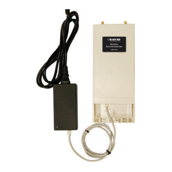
- Page 6 Chapter 2: Preparing for Installation Figure 2-1. Pole-mounting ring. Figure 2-2. Power cord and PoE injector. Figure 2-3. Ferrite suppression core. Page 6 724-746-5500 | blackbox.com...
-
Page 7: Chapter 3: System Installation
Chapter 3: System Installation 3. System Installation Connect up 1. The bottom of the Wireless Ethernet Extender is a movable cover. Grab the cover and pull it back harder to take it out as the figure shown below. Figure 3-1. Removing the bottom cover from the extender. 2. - Page 8 Chapter 3: System Installation Using the Grounding Wire The extender has a grounding wire. Be sure to connect the extender, cables, and PoE injector to earth ground properly during normal use to protect against surges or ESD. 1. Remove the screw on the grounding point at the bottom of the Wireless Ethernet Extender.
- Page 9 Chapter 3: System Installation Install the External Antenna The Wireless Ethernet Extender provides two reverse SMA antenna connectors for connecting the external antennas. Figure 3-6. External antenna connectors. 1. Connect your external antennas to the SMA-type connectors on top of the Wireless Ethernet Extender.
- Page 10 Chapter 3: System Installation 2. Bend the antenna to 90 degrees or 45 degrees. 90° 45° Figure 3-8. Bend antenna. 3. You may turn one antenna 45 degrees to the left and the other 45 degrees to the right. The tilted antennas couple together much less than if they are both pointed in the same direction.
- Page 11 Chapter 3: System Installation 5. To adjust antennas, loosen the connector joint counterclockwise first, then adjust the antenna to the desired position. DO NOT bend or turn the antennas without loosening the connector joint; otherwise, you might damage the antennas. 6.
- Page 12 Chapter 3: System Installation 2. Mount the Wireless Ethernet Extender steadily to the pole by locking the pole mounting ring tightly. Figure 3-12. Extender mounted on a pole. Power Up 1. Plug the power cord into the DC port of the PoE injector. Figure 3-13.
- Page 13 Chapter 3: System Installation 3. Use an Ethernet cable to connect the Wireless Ethernet Extender to the “POE” port of the PoE injector as shown below. Figure 3-14. Power up the extender. 4. Connect the power plug to a power socket. The Wireless Ethernet Extender will be powered up immediately.
- Page 14 Chapter 3: System Installation 2. Lay the Ethermet cable into the core, usually within 2 to 3 inches of the connector. Figure 3-16. Putting cable into the core. 3. Loop the cable around and through the core. This helps “lock” the core in place, and may be required in circumstances withe severe interference.
- Page 15 Chapter 3: System Installation 4. Close the core and snap the halves back together. Figure 3-18. Close core. 5. Connect the Ethernet cable with suppression core to the “Data In” port of the PoE injector. Data in Figure 3-19. Connecting cable to data-in port. Page 15 724-746-5500 | blackbox.com...
- Page 16 Chapter 3: System Installation 6. Connect the other end of the Ethernet cable to a PC or a switch hub. The harware installation is complete. Figure 3-20. Completed installation. Page 16 724-746-5500 | blackbox.com...
-
Page 17: Chapter 4: Configuration
Chapter 4: Configuration 4. Configuration The Wireless Ethernet Extender covers “Thin AP mode,” “AC+Thin AP mode,” and “FAT AP mode.” The default mode is Thin AP. To allow the Wireless Ethernet Extender to manage the thin APs, you need to switch one of the Wireless Ethernet Extender to virtual controller mode first. - Page 18 Chapter 4: Configuration Figure 4-2. Address bar. 4. You will now see the login page of the Wireless Ethernet Extender. The default “Name” and “Password” are “admin” and “password,” respectively. Enter them and then click “Login.” NOTE: The login page (not shown) contains a space where you can enter the default Name (admin) and the default password (password).
- Page 19 Chapter 4: Configuration Configure the AC+Thin AP mode 5. To operate as AC+Thin AP mode, go to Basic Settings. From the Device Mode drop-down list, select “Virtual AC” mode. To use the extender as a virtual controller and access point concurrently, select “Virtual AC + Thin AP” mode. Then assign an IP address to the Wireless Ethernet Extender and specify subnet mask, gateway, and DNS address, respectively.
- Page 20 Chapter 4: Configuration Figure 4-5. Wireless Networks screen. The wireless setting will also apply to the VAC-managed APs. A dialog message will pop up to remind you changes will also apply to other extender-managed APs. Click “Apply” to apply the configuration immediately. Figure 4-6.
- Page 21 Chapter 4: Configuration Figure 4-7. Configuration file screen. Firmware Upgrade for Ethernet Extender in AC mode To upgrade the firmware for the Wireless Ethernet Extender in AC mode, go to Management —> Firmware Upload and from Upgrade AC Firmware, browse the firmware file where it is placed.
- Page 22 Chapter 4: Configuration Figure 4-9. AP Management screen, Registered APs highlighted. Moving the mouse over MAC address of each managed AP will also display rele- vant RF infofmation such as channel mode, current channel, antenna being used, and transmit output power. Figure 4-10.
- Page 23 Chapter 4: Configuration Manage the extender-managed APs To configure and manage the managed APs: 1. Enter the web page of the Wireless Ethernet Extender in AC mode and go to Management —> AP Management. The following screen appears. Figure 4-11. AP Management screen. The Wireless Ethernet Extender AP in Virtual AC+Thin AP mode on the list is highlighted in bold font.
- Page 24 Chapter 4: Configuration Figure 4-13. AP Management screen, Radio button highlighted. To configure managed APs individually, select the one you want to manage and press the “Radio” button. Figure 4-14. AP Management screen, APs managed by AC hightlighted. Besides radio setting, you may also reboot the managed AP, change its IP address, and upgrade the firmware for a managed AP.
- Page 25 Chapter 4: Configuration Firmware Upgrade for the Ethernet Extender in AC mode For firmware upgrade, you may choose to upgrade the selected managed AP by pressing “Upgrade Selected,” or do the group upgrade by pressing “Upgrade All.” Before upgrading the managed AP, you need to locate the new firmware in the Wireless Ethernet Extender.
- Page 26 Chapter 4: Configuration Figure 4-17. AP Management screen, Upgrade. Monitor the Ethernet Extender-Managed AP To view each managed AP’s status, go to Status —> Managed APs. Besides view- ing device information such as device name, MAC address, IP address, and FW version, you may also monitor the wireless clients that are currently associated with the managed APs as well as packets statistics.
- Page 27 Chapter 4: Configuration Figure 4-19. System settings. To switch from default mode Thin AP to Fat AP mode for the first time configura- tion, go to Basic Settings. From the Device Mode drop-down list, select “Fat AP” and press “YES” to make the change take effect. Figure 4-20.
- Page 28 Chapter 4: Configuration AP Mode 1. Choose Wireless —> Basic Settings. The default is AP mode already. Here, you can set the parameters to optimize your application, or you can leave them as the default. Click “Apply” to save the parameters. NOTE: In the example here, we only change the “Wireless Network Name (SSID)”...
- Page 29 Chapter 4: Configuration 3. You may set the parameters such as “Network Authentication” and “Data Encryption” for more secure network communication in your application. Click “Apply” to save the parameters. Figure 4-23. VAP Profile1 Settings screen. 4. To decrease the chances of data retransmission at long distances, the extender can automatically adjust the proper ACK timeout value by specifying distance between the nodes.
- Page 30 Chapter 4: Configuration Wireless Client Mode 1. Choose Wireless —> Basic Settings. Then you will see the “Wireless Basic Settings” page. Choose “Wireless Client” from Wireless Mode, and click “Apply” to save it. You can then change the other parameters to optimize your application before clicking “Apply.”...
- Page 31 Chapter 4: Configuration Figure 4-27. Wireless Site Survey screen. 3. If the AP you connect to require authentication or encryption keys, click “Profile Settings” in the left column, fill out the corresponding items, and click “ Apply” for data encryption. Figure 4-28.
-
Page 32: Bridge Mode
Chapter 4: Configuration Bridge Mode 1. Choose Wireless —> Basic Settings. Then you will see the “Wireless Basic Settings” page. Choose “Bridge” from Wireless Mode, and click “Apply” to save it. You can change the other parameters to optimize your application before clicking “Apply.”... - Page 33 Chapter 4: Configuration 3. Repeat the above procedures to configure the remote IEEE 802.11b/g/n Wireless Ethernet Extender. 4. Enter the actual distance in meters. For example, if the distance between the two VAC bridges is 3 kilometers, enter 3000 in the field. 5.
- Page 34 Chapter 4: Configuration Figure 4-33. Wireless Basic Settings screen. To establish a point-to-point bridge connection, follow the procedures described in Bridge mode. To connect the wireless client to the AP, follow the procedures described in Wireless Client mode. Page 34 724-746-5500 | blackbox.com...
- Page 35 NOTES Page 35 724-746-5500 | blackbox.com...
- Page 36 724-746-5500 or blackbox.com. About Black Box Black Box provides an extensive range of networking and infrastructure products. You’ll find everything from cabinets and racks and power and surge protection products to media converters and Ethernet switches all supported by free, live 24/7 Tech support available in 60 seconds or less.
Need help?
Do you have a question about the LWE121A and is the answer not in the manual?
Questions and answers