Graco Husky 2150 Instructions-Parts List Manual

Graco Husky 2150 Instructions-Parts List Manual

Air–operated diaphragm pumps
Hide thumbs Also See for Husky 2150:

Advertisement

Quick Links

Instructions – Parts List
Parts
ALUMINUM, STAINLESS, AND DUCTILE IRON
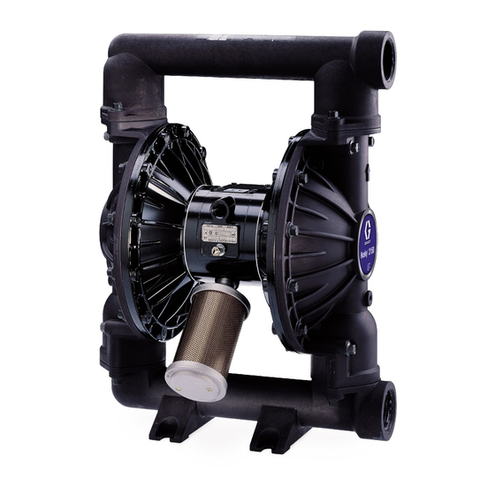
Huskyt2150 Air–Operated
Diaphragm Pumps
120 psi (0.8 MPa, 8 bar) Maximum Fluid Working Pressure
120 psi (0.8 MPa, 8 bar) Maximum Air Input Pressure
*Model No. DF3
*Model No. DFH
*Model No. DF4
*Model No. DF6
*Model No. DFC
*Model No. DFD
*Model No. DFF
*Model No. DFJ
Model No. 232503
*NOTE: Refer to the Pump Matrix on page 20 to
determine the Model No. of your pump.
US and Foreign Patents Pending
Read warnings and instructions.
See page 2 for table of contents.
GRACO INC. P.O. BOX 1441 MINNEAPOLIS, MN 55440-1441
Copyright 1994, Graco Inc. is registered to I.S. EN ISO 9001
Aluminum Pumps
Aluminum Extended Pump
Stainless Steel Pumps
Ductile Iron Pumps
Aluminum BSPT Pumps
Stainless Steel BSPT Pumps
Ductile Iron BSPT Pumps
Aluminum BSPT Extended Pump
Private-Label Aluminum
2150 Pump (See page 20.)
Aluminum Model Shown
308368W
03940B

Advertisement

Table of Contents
loading

Summary of Contents for Graco Husky 2150

  • Page 1 Model No. of your pump. US and Foreign Patents Pending Read warnings and instructions. See page 2 for table of contents. Aluminum Model Shown 03940B GRACO INC. P.O. BOX 1441 MINNEAPOLIS, MN 55440-1441 Copyright 1994, Graco Inc. is registered to I.S. EN ISO 9001...
  • Page 2: Table Of Contents

    D Never alter or modify any part of this equipment; doing so could cause it to malfunction. Use only genuine Graco parts and accessories. D Check all equipment regularly and repair or replace worn or damaged parts immediately.
  • Page 3 WARNING HAZARDOUS FLUIDS Improper handling of hazardous fluids or inhaling toxic vapors can cause extremely serious injury, even death, due to splashing in the eyes, ingestion, or bodily contamination. Observe all the follow- ing precautions when handling known or potentially hazardous fluids. D Know what fluid you are pumping and its specific hazards.
  • Page 4: Installation

    Fig. 1. Loosen the grounding screw (W). Insert D Always use Genuine Graco Parts and Accessories. one end of a 12 ga (1.5 mm@) minimum ground wire (Y) behind the grounding screw and tighten the D Reference numbers and letters in parentheses refer screw securely.
  • Page 5 3. Connect remaining ends of tubes to external air valve and the pump. Trapped air can cause the signal, such as Graco’s Cycleflo (P/N 195264) or pump to cycle unexpectedly, which could result in Cycleflo II (P/N195265) controllers.
  • Page 6 Installation Fluid Outlet Line 2. Install a fluid drain valve (J) near the fluid outlet. See the WARNING above. WARNING 3. Install a shutoff valve (K) in the fluid outlet line. A fluid drain valve (J) is required to relieve pres- Retorquing with TeflonR Seals or sure in the hose if it is plugged.
  • Page 7 Installation Changing the Orientation of the Fluid Inlet Fluid Pressure Relief Valve and Outlet Ports CAUTION The pump is shipped with the fluid inlet (R) and outlet (S) ports facing the same direction. See Fig. 3. To Some systems may require installation of a pres- change the orientation of the inlet and/or outlet port: sure relief valve at the pump outlet to prevent overpressurization and rupture of the pump or...
  • Page 8 Installation Air Exhaust Ventilation The air exhaust port is 3/4 npt(f). Do not restrict the air WARNING exhaust port. Excessive exhaust restriction can cause erratic pump operation. FIRE AND EXPLOSION HAZARD; HAZARDOUS FLUIDS To provide a remote exhaust: Be sure to read and follow the warnings and precautions regarding HAZ- 1.
  • Page 9: Operation

    Operation Flush the Pump Before First Use Operation of Remote Piloted Pumps The pump was tested in water. If the water could 1. Fig. 2 and Parts Drawings. Follow preceding steps contaminate the fluid you are pumping, flush the pump 1 through 7 of Starting and Adjusting Pump.
  • Page 10: Maintenance

    Maintenance Lubrication Tightening Threaded Connections The air valve is designed to operate unlubricated, Before each use, check all hoses for wear or damage, however if lubrication is desired, every 500 hours of and replace as necessary. Check to be sure all operation (or monthly) remove the hose from the pump threaded connections are tight and leak-free.
  • Page 11: Troubleshooting

    Troubleshooting WARNING To reduce the risk of serious injury, including splashing fluid in the eyes or on the skin, follow the Pressure Relief Procedure on page 9 when this manual instructs you to relieve pressure, when you shut off the pump, and before checking, adjusting, cleaning, moving, or repairing any system equipment.
  • Page 12: Repairing The Air Valve

    Service Repairing the Air Valve Tools Required D Torque wrench D Torx (T20) screwdriver or 7 mm (9/32”) socket wrench D Needle-nose pliers D O-ring pick D Lithium base grease NOTE: Air Valve Repair Kit 236273 is available. Refer to page 22. Parts included in the kit are marked with a symbol, for example (4{).
  • Page 13 Service Reassembly 1. If you removed the bearings (12, 15), install new Insert narrow end first. ones as explained on page 18. Reassemble the fluid section. Grease. Install with lips facing narrow end of piston (11). Insert wide end first. 2.
  • Page 14: Ball Check Valve Repair

    Service Ball Check Valve Repair Apply medium-strength (blue) LoctiteR or equivalent to the threads. Torque to 120 to 150 in-lb Tools Required (14 to 17 N.m). Arrow (A) must point toward outlet manifold (103). D Torque wrench Not used on some models. D 10 mm socket wrench Beveled seating surface must face ball (301).
  • Page 15: Diaphragm Repair

    Service Diaphragm Repair Disassembly NOTE: A Fluid Section Repair Kit is available. Refer to Tools Required page 21 to order the correct kit for your pump. Parts D Torque wrench included in the kit are marked with an asterisk, for example (401*).
  • Page 16 Service 4. Loosen but do not remove the diaphragm shaft c. On TeflonR Models only, install the TeflonR bolts (107), using a 15 mm socket wrench (1” on diaphragm (403*). Make certain the side stainless steel models) on both bolts. marked AIR SIDE faces the center housing (1).
  • Page 17 Service 402* 403* 401* 03981A 03982A Cutaway View, with Diaphragms in Place Cutaway View, with Diaphragms Removed 401* 403* 108* Lips face out of housing (1). Rounded side faces diaphragm (401). Air Side must face center housing (1). Grease. Apply medium-strength (blue) LoctiteR or equivalent. Torque to 20 to 25 ft-lb (27 to 34 N.m) at 100 rpm maximum.
  • Page 18: Bearing And Air Gasket Removal

    Service Bearing and Air Gasket Removal Tools Required 7. Use a bearing puller to remove the diaphragm shaft bearings (19), air valve bearings (12) or pilot D Torque wrench pin bearings (15). Do not remove undamaged bearings. D 10 mm socket wrench 8.
  • Page 19 Service Insert bearings tapered end first. Press-fit bearings flush with surface of center housing (1). Apply medium-strength (blue) LoctiteR or equivalent to the threads. Torque to 120 to 150 in-lb (14 to 17 N.m). 16 H 03951 Detail of Air Valve Bearings 03952B Fig.
  • Page 20: Pump Matrix

    Pump Matrix Husky 2150 Aluminum, Stainless Steel, and Ductile Iron Pumps, Series A Your Model No. is marked on the pump’s serial plate. To determine the Model No. of your pump from the following matrix, select the six digits which describe your pump, working from left to right. The first digit is always D, designating Husky diaphragm pumps.
  • Page 21: Repair Kit Matrix

    Repair Kit Matrix For Husky 2150 Aluminum and Stainless Steel Pumps, Series A Repair Kits may be ordered separately. To repair the air valve, order Part No. 236273 (see page 22). Parts included in the Air Valve Repair Kit are marked with a symbol in the parts list, for example (4{).
  • Page 22: Parts

    Parts 11 10{ Aluminum Model Shown 401* 301* 403* 201* 202* 108* *402 *301 *201 202* Not used on some models TI0353B Used on stainless steel model only Z117 Extension * These parts are included in the Pump Repair Kit, which may be purchased separately.
  • Page 23 Parts Air Motor Parts List (Matrix Column 2) Fluid Section Parts List (Matrix Column 3) Ref. Ref. Digit Part No. Description Digit Part No. Description 15A612 COVER, fluid; aluminum 188838 HOUSING, center; alum. 195921 HOUSING, center;remote 189302 MANIFOLD, inlet; aluminum 188854 COVER, air valve;...
  • Page 24 Fluid Section Parts List (Matrix Column 3) Ref. Ref. Digit Part No. Description Digit Part No. Description 194279 COVER, fluid; 15A612 COVER, fluid; aluminum 316 stainless steel 192086 MANIFOLD, inlet; aluminum; BSPT 194280 MANIFOLD, inlet; 316 stainless steel 15A614 MANIFOLD, outlet; aluminum;...
  • Page 25 Parts Fluid Section Parts List (Matrix Column 3) Diaphragm Parts List (Matrix Column 6) continued Ref. Digit Part No. Description 191541 COVER, fluid; ductile iron 401* 189296 DIAPHRAGM, backup; 192088 MANIFOLD, inlet; SantopreneR ductile iron; BSPT 402* 112181 PACKING, u-cup; nitrile 192089 MANIFOLD, outlet;...
  • Page 26: Dimensions

    Dimensions ‘ FRONT VIEW PUMP MOUNTING HOLE PATTERN four 0.625 in. (16 mm) diameter holes 6.0 in. 1/2 npt(f) (152.5 mm) air inlet 3/4 npt(f) air exhaust (muffler included) SIDE VIEW 6.25 in. (158.8 mm) 2 in. (50.8 mm) port diameter 6.0 in.
  • Page 27 Dimensions ‘ Aluminum Pumps Aluminum Extension Ductile Iron Pumps Stainless Steel Dimension Pumps* Pumps 8.39 in. (213.1 mm) 8.39 in. (213.1 mm) 8.39 in. (213.1 mm) 8.73 in. (222.7 mm) 9.06 in. (230.1 mm) 9.06 in. (230.1 mm) 9.06 in. (230.1 mm) 9.41 in.
  • Page 28: Technical Data

    Technical Data Maximum fluid working pressure ..............120 psi (0.8 MPa, 8 bar) Air pressure operating range...
  • Page 29: Performance Chart

    Performance Chart Example of Finding Pump Air Consumption and Air Pressure at a Specific Fluid Delivery and Discharge Head: To supply 60 gpm (227 liters) fluid flow (horizontal scale) at 40 psi (0.28 MPa, 2.8 bar) discharge head pressure (vertical scale) requires approximately 60 scfm (1.68 m /min) air consumption at 70 psi (0.49 MPa, 4.9 bar) inlet air pressure.
  • Page 30: Graco Warranties

    Graco distributor to the original purchaser for use. With the exception of any special, extended, or limited warranty published by Graco, Graco will, for a period of five years from the date of sale, repair or replace any part of the equipment determined by Graco to be defective.

This manual is also suitable for:

Df3DfhDf4Df6DfcDfd ... Show all

Table of Contents