Table of Contents
Advertisement
Quick Links
Advertisement
Table of Contents

Subscribe to Our Youtube Channel
Related Manuals for Kubota F5205


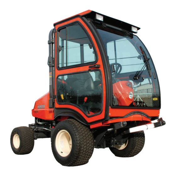
Summary of Contents for Kubota F5205
- Page 1 Rev. C p. 1 of 21 F5205 HARD SIDED CAB KIT INSTALLATION & OWNER’S MANUAL The contents of this envelope are the property of the owner. Be sure to leave with the owner when installation is complete. Cab is supplied with Work Lights and Windshield Wiper.
- Page 2 PAGE 2 OF 21 This cab is designed and manufac- Exposure to Carbon Monoxide WARNING WARNING tured for use only as reasonable can Cause illness, serious injury weather protection. This cab is not applicable, nor should or death. Never operate vehicle if suspicious of Carbon the cab be considered as protection against roll over, col- Monoxide.
- Page 3 Reference Kubota mower service manual for a more detailed description. 1.2 Remove the grab handle from the left side by remov- ing the two (2) hex nut/washer combinations (SEMS) from underneath the fender.
- Page 4 PAGE 4 OF 21 1. DECK SOUND BARRIER (cont’d.) Use of the supplied plastic pine tree clips and fender washers (qty.: 16 of ea.) is strongly advised to help secure the sound material around the bends in the fender and will help prevent the sound material from premature- ly coming loose.
- Page 5 PAGE 5 OF 21 VEHICLE PREP. 2.2 Have one 10mm x 1.25 x 20mm long hex head bolt ready. Remove one of the two large clamping hand knobs from the middle of the upright of the roll bar while holding the “U” shaped bracket in place. See figures 2.2 and 2.2.1.
- Page 6 PAGE 6 OF 21 LOWER REAR PANEL lower rear panel With assistance, install the lower rear panel onto the threaded shafts of the two rubber bumpers. Use 3/8” locknuts and washers as shown in fig. 5.1. Tighten both locknuts. Do not peel off the backing paper on the sound barrier material until step 7 (just prior to installing the upper rear panel assembly).
- Page 7 PAGE 7 OF 21 8. COWL 8.1 With assistance, install the cowl to the lower front of the side frames. Use two 5/16” x 3/4” long button head bolts, two steel washers, and two plastic washers per side to connect to the factory installed threaded button head bolts, inserts in the side frame tubing.
- Page 8 PAGE 8 OF 21 11. REAR PANEL 11.1 Attach rear panel to the left and right side frames with eight 5/16-18 x 3/4” long button head bolts and steel washers (four per side) into factory installed threaded inserts. See figure 11.1. 12.
- Page 9 PAGE 9 OF 21 14. WINDSHIELD 14.1 Install the 3/4” thick plastic spacers onto the wind- shield hinges and insert four 5/16” x 1 3/4” long flat head bolts. See figure 14.1. 14.2 With assistance, lift the windshield in place and engage the bolts into the slots.
- Page 10 PAGE 10 OF 21 17. FINAL WIRING (cont’d.) 17.2 Route the wiper wire harness (black plug on one end) down the steering column and back to the battery. Drill a 3/8” hole in the vehicle steering column cover (Note: Be sure to check for clearance inside the col- umn, do not drill too deep) and feed the harness through the hole, and down the inside of the steering column.
- Page 11 PAGE 11 OF 21 18. WINDSHIELD WIPER CAUTION: Make sure that the metal parts of the wiper motor do not contact the glass during installation. Damage could occur. WARNING: Over tightening wiper mounting hardware can damage windshield and components. 18.1 Install the pantograph wiper motor as shown below in figure 18.1. Install blade to arm and arm to wiper motor. A factory installed set screw has been provided to ensure that the arm does not work its way off the splined shaft of the motor.
- Page 12 P. 12 OF 21 F5205 HARD SIDED CAB KIT PARTS LIST FOR ROOF QTY. DESCRIPTION...
- Page 13 P. 13 OF 21 F5205 HARD SIDED CAB KIT PARTS LIST FOR WINDSHIELD...
- Page 14 P. 14 OF 21 F5205 HARD SIDED CAB KIT PARTS LIST FOR REAR PANEL ASSEMBLY...
- Page 15 P. 15 OF 21 F5205 HARD SIDED CAB KIT PARTS LIST FOR WINDSHIELD SUPPORT AND COWL...
- Page 16 P. 16 OF 21 F5205 HARD SIDED CAB KIT PARTS LIST FOR LOWER REAR PANEL AND LOWER REAR MOUNT...
- Page 17 P. 17 OF 21 F5205 HARD SIDED CAB KIT PARTS LIST FOR FRONT MOUNTS AND ROLL BAR BRACKETS...
- Page 18 P. 18 OF 21 F5205 HARD SIDED CAB KIT PARTS LIST FOR SIDE FRAMES...
- Page 19 P. 19 OF 21 F5205 HARD SIDED CAB KIT PARTS LIST FOR HARD SIDED DOORS...
- Page 20 P. 20 OF 21 F5205 HARD SIDED CAB KIT PARTS LIST FOR WIPER O.L. = obtain locally...
- Page 21 P. 21 OF 21 PARTS LIST FOR SOUND REDUCTION KIT...
Need help?
Do you have a question about the F5205 and is the answer not in the manual?
Questions and answers