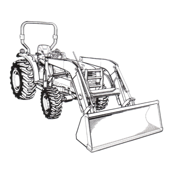
Kubota LA513 Assembly Instructions Manual
Hide thumbs
Also See for LA513:
- Operator's manual (39 pages) ,
- Assembly instructions manual (16 pages)
Summary of Contents for Kubota LA513
-
Page 2: Table Of Contents
CONTENTS 1. To the Dealer ................. 2. Safety ..................... 1 3. Unpacking and Checking Parts ........... 2 Unpacking Wooden Crate ..........Checking Parts ............... 4. Tractor Preparation ............... 4 5. Assembly ..................4 Boom Assembly ................Boom Assembly with Quick Hitch (Option) ......... Main Frame ................. -
Page 3: To The Dealer
1. TO THE DEALER 3. Working clothes which may be pinched caught (1) This manual contains procedures intended to assist equipment must not be worn. the dealer in unpacking and assembling the product Loose clothing cause before delivering to the customer. serious injury or death. -
Page 4: Unpacking And Checking Parts
(3) After assembly check 3. Raise the upper part of crate and remove from the 1. Before operating or test-driving immediate area. equipment, read 4. Remove the remaining slats from the crate. understand operator’s These are indicated by the oblique lines in manual. -
Page 5: Checking Parts
3.2CHECKING PARTS Remove all loader components. Referring to the illustration, insure that all components have been included. (1) Boom assembly (2) Main frame LH (3) Main frame RH (4) Front guard (5) Sub frame (6) Level indicator (7) Control valve assembly [L2203,L2213,L2213A] (8) Control valve assembly [L2223,L2223A]... -
Page 6: Tractor Preparation
4. TRACTOR PREPARATION Boom Assembly 1. Attach the bucket to the boom and bucket links as 1. Remove the mid mount mower from the tractor if shown. equipped. 2. Locate the tractor on a firm level surface. Lower the implement to the ground, set the parking brake and stop the engine. -
Page 7: Boom Assembly With Quick Hitch (Option)
4. Rotate the stands until the pin on the stand and hole 2. Raise the boom until the stands can be rotated. in the boom are aligned. Then slide the stands outward and insert the spring pin as shown. (1) Nylon band 3. -
Page 8: Hydraulic Line
(3) 10-M16X45 bolts 10-M16 spring lock washers Tightening torque : 23kgf-m (166 ft-lbs) Re-route the hoses position. (LA513, LA723 for L3430 CAB type) 1. Before the main frame of front loader is attached to the tractor, remove the clamp from the tractor frame. - Page 9 4. Connect the hose from “Pump port” on the control IMPORTANT: valve assembly to “Pump port” on the hydraulic • Hoses pre-installed on the control valve assembly are block. not securely tightened to ease installation of hoses to 5. Connect the hose from “Tank port” on the control hydraulic block.
-
Page 10: Sub Frame
Sub Frame 1. Attach the sub frame to the main frame as shown. (1) Sub frame [LA513] (2) 6-M16 x 50 bolts 6-M16 spring lock washers 6-5/8 hardened plain washers [LA723, LA853] (2) 6-M16 x 55 bolts 6-M16 spring lock washers... -
Page 11: Front Guard
4. Slide the rubber boot up the control lever to expose Front Guard the cable ends. Disassemble the control lever and 1. Remove the front bumper from the front axle frame, cable ends from the controller by loosening the if equipped. socket head cap screw at the control lever pivot. - Page 12 6. Screw the cables into the controller and lock the NOTE: cables in the neutral position by using lock lever and • To aid in assembly of the control lever, install the groove. boom section cable end first and the bucket section cable end second.
-
Page 13: Bucket Level Indicator
Bucket Level Indicator 1. Install the cir-clip on the bucket cylinder pivot pin. (1) Cir-clip (2) Bucket pivot pin 2. Install guide, rod, and cir-clip as shown. NOTE: • Adjust hose direction not to touch the rod. (1) Rod (2) Guide (3) Cir-clip (4) Split pin (5) M8 plain washer... -
Page 15: Template For Controller Assembly
6.TEMPLATE FOR CONTROLLER ASSEMBLY... -
Page 17: Pre-Operation Check
2. Impact wrench, Ratchet wrench, Torque wrench, Socket wrench, Spanner wrench. 3. Nylon strap. Standard valve Remote valve type Loader type Loader LA513 LA723 1.5 hour 1.9 hour LA853 Transmission Fluid Check tractor transmission fluid level. Add fluid if necessary. Refer to the tractor operator’s manual for instructions and proper fluid. -
Page 18: Tightening Torque Of Bolts And Nuts
9.TIGHTENING TORQUE OF BOLTS AND NUTS General torque specification American standard screws, bolts and nuts with UNC or Metric cap screws UNF threads SAE grade No. SAE GR.5 SAE GR.8 property class 8.8 Approx. SAE GR 5 (N-m) 11.7 to 15.8 16.3 to 19.8 (N-m) 9.8 to 11.2...


Need help?
Do you have a question about the LA513 and is the answer not in the manual?
Questions and answers