
Related Manuals for Kubota V4291


Summary of Contents for Kubota V4291
- Page 1 72" V-BLADE MODEL V4291 FOR RTV900 & RTV1100 Series SERIAL NO. 2903531 AND UP OM 0387VB-A MANUAL PART NUMBER 77700-01200 04/09...
-
Page 3: Table Of Contents
TABLE OF CONTENT INTRODUCTION – To the Purchaser ....................2 SAFETY PRECAUTIONS ........................3 Before Operation ..........................3 Notice .............................4 The Blade ............................4 Before Operation ......................4 Blade Operation........................5 The Vehicle .............................6 General Information ......................6 Operating the Vehicle .......................6 During Operation ......................6 Maintenance ...........................7 Storage ............................7 DECALS ...............................8 ASSEMBLY ............................10... -
Page 4: Introduction - To The Purchaser
INTRODUCTION O THE URCHASER All products are designed to give safe, Illustrations dependable service if they are operated and maintained according to instructions. Read The illustrations may not necessarily reproduce understand this manual before the full detail and the exact shape of the parts operation. -
Page 5: Safety Precautions
SAFETY PRECAUTIONS SAFETY FIRST This symbol, the industry's "Safety Alert Symbol", is used throughout this manual and on labels on the machine itself to warn of the possibility of personal injury. Read these instructions carefully. It is essential that you read the instructions and safety regulations before you attempt to assemble or use this unit. -
Page 6: Notice
SAFETY PRECAUTIONS - continued OTICE A safe operator is the best assurance against accidents. All operators, no matter how experienced they may be, should read this operator's manual and all other related manuals before attempting to operate the equipment. Please read the following section and pay particular attention to all safety recommendations contained in this manual and those labeled on the equipment and on the vehicle. -
Page 7: Blade Operation
SAFETY PRECAUTIONS - continued Blade Operation 1. Before leaving the vehicle unattended, take 9. Never operate machine at high transport possible precautions. Park speeds on a slippery surface. vehicle/blade on level ground, set the 10. Use extra caution when backing up. parking brake, lower the equipment to the 11. -
Page 8: The Vehicle
SAFETY PRECAUTIONS - continued EHICLE General Information 11. Fill fuel tank outdoors with extreme care. Never fill fuel tank indoors. Replace fuel 1. Read the operator's manual carefully before cap securely and wipe up spilled fuel. using vehicle. Lack of operating knowledge can lead to accidents. -
Page 9: Maintenance
SAFETY PRECAUTIONS - continued AINTENANCE ALWAYS USE GENUINE PARTS WHEN 9. Do not modify or alter this blade or any of REPLACEMENT PARTS ARE REQUIRED its components or operating functions. If have questions concerning 1. Keep the vehicle and blade properly modifications, consult with your dealer. -
Page 10: Decals
DECALS FOR KUBOTA USA Replace Immediately if Damaged 77700-01229 (2500758) 77700- 01230 (2500759) 70060-02232 (2500484) 70060-03033 (658710) 70060-01448 (657524) OM 0387VB-A... - Page 11 DECALS FOR KUBOTA CANADA Replace Immediately if Damaged 70060-03033 70060-03762 (658710) (660990) 70060-01396 (657525) 77700-01229 (2500758) 70060-01448 (657524) 77700-01231 (2500760) 70060-02232 (2500484) 70060-03033 70060-03762 (658710) (660990) OM 0387VB-A...
-
Page 12: Assembly
ASSEMBLY LADE NSTALLATION Mounting the Blade on the Vehicle (Figure 1) 1. Insert the male quick hitch (item 1) into the 3. Connect the blade hoses to the male female quick hitch (item 2), turn the engine couplers of the hydraulic system installed off and set the parking brake. -
Page 13: Operation
OPERATION LADE PERATION The blade has been designed so the cutting edge pivots towards the back when it hits an obstacle. Once the blade clears the obstacle, the cutting edge will return to its normal position. Raising, Lowering and Angling the Blade Skid Shoe Adjustment (Figure 3) Refer to the Operator's Manual of the hydraulic... -
Page 14: Adjusting The Tilt System And The Middle Cutting Edges
OPERATION Adjusting the Tilt System and the Middle Cutting Edges (Figure 4) Figure 4 To maintain the cutting edges parallel with the ground, adjusting the tilt is necessary to compensate for cutting edge wear and the height of the vehicle. This adjustment must be performed on flat and leveled grounds. -
Page 15: Inverting The Cutting Edges
OPERATION - MAINTENANCE Inverting the Cutting Edges Figure 7 (Figure 7) When the cutting edges are worn, remove the 5/8"NC x 1 1/2" cutting edges (item 1), the 5/8"NC nuts (item 2) and the 5/8" flat washers (item 3). Turn the cutting edge 180° (item 4) and reinstall the hardware. -
Page 16: Parts
PARTS NTRODUCTION All parts are illustrated in "exploded views" which show the individual parts in their normal relationship to each other. Reference numbers are used in the illustrations. These numbers correspond to those in the "Reference Number" (REF) column, and are followed by the description and quantity required. "Right Hand"... -
Page 17: Hitch And Tilt System
PARTS ITCH AND YSTEM ESCRIPTION Quick hitch 77700-01215 668912 Tilt system 77700-01216 668913 Adjustment arm 77700-01217 668914 Pin 1 1/2" x 7 19/32" lg., PTD 77700-01234 668925 Bolt hex. 1/4"NC x 2 1/2" lg gr.5 PTD 75599-01150 0100012 Nut nylon insert 1/4"NC PTD 75599-31911 1000003 Bolt hex. -
Page 18: Right Blade Assembly
PARTS IGHT LADE SSEMBLY OM 0387VB-A... - Page 19 PARTS IGHT LADE SSEMBLY ESCRIPTION Blade - RH 77700-01213 668909 Snow deflector 77700-01212 668756 Bolt hex. 5/16" NC x 1" lg. Gr.5, PTD 75599-01220 0100019 Bushing 77700-01251 668969 Nut nylon insert 5/16"NC PTD 75599-31912 1000005 Bolt 5/8" dia. X 1 3/4" lg. gr. 5 PTD 77700-01254 0100094 Flat washer 7/16"...
-
Page 20: Left Blade Assembly
PARTS LADE SSEMBLY OM 0387VB-A... - Page 21 PARTS LADE SSEMBLY ESCRIPTION Blade - LH 77700-01214 668911 Snow deflector 77700-01212 668756 Bolt hex. 5/16" NC x 1" lg. Gr.5, PTD 75599-01220 0100019 Bushing 77700-01251 668969 Nut nylon insert 5/16"NC PTD 75599-31912 1000005 Bolt 5/8" dia. X 1 3/4" lg. gr. 5 PTD 77700-01254 0100094 Flat washer 7/16"...
-
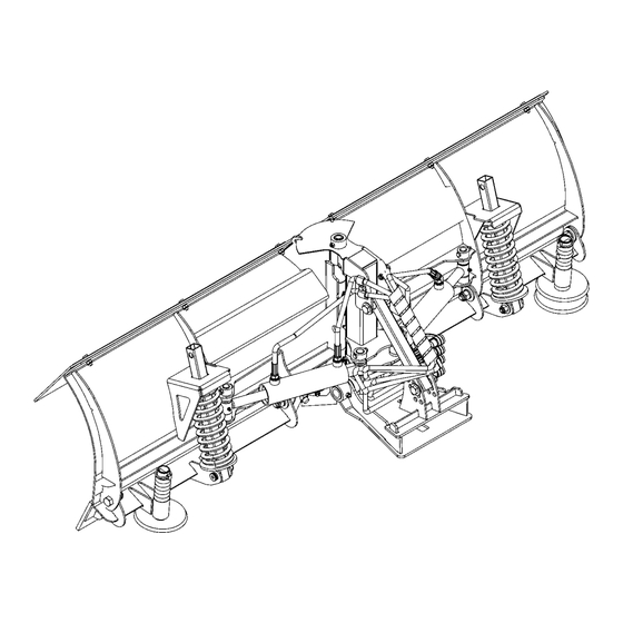
Page 22: Hydraulic Components
PARTS YDRAULIC OMPONENTS OM 0387VB-A... - Page 23 PARTS YDRAULIC OMPONENTS ESCRIPTION Cylinder 2" x 6 1/2" 70001-00636 664979 Grease fitting 1/4" NF 70060-00940 654106 Seal Kit 70001-00660 665017 Grease fitting 1/4" - 45° 70060-02853 657749 Pin 3/4" x 4 3/8" lg, PTD 77700-01225 668923 Nut nylon insert 1/4"NC PTD 75599-31911 1000003 Bolt hex.
-
Page 24: Torque Specification Table
TORQUE SPECIFICATION TABLE GENERAL SPECIFICATION TABLE Use the following torques when special torques are not given. Note: These values apply to fasteners as received from supplier, when dry. These values do not apply if lubricants are used. BOLT SIZES (SAE) TORQUE INCHES Pounds-Foot... - Page 28 Printed in Canada...
Need help?
Do you have a question about the V4291 and is the answer not in the manual?
Questions and answers