Sign In
Upload
Manuals
Brands
Baker Hughes Manuals
Valve Positioners
Masoneilan SVIII AP
Baker Hughes Masoneilan SVIII AP Valve Manuals
Manuals and User Guides for Baker Hughes Masoneilan SVIII AP Valve. We have
1
Baker Hughes Masoneilan SVIII AP Valve manual available for free PDF download: Installation And Maintenance Manual
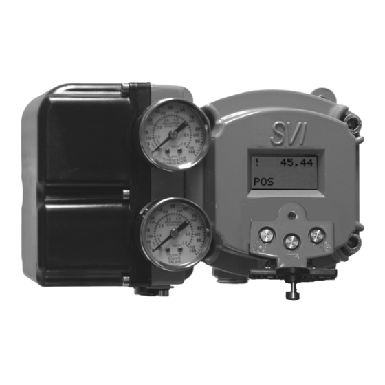
Baker Hughes Masoneilan SVIII AP Installation And Maintenance Manual (204 pages)
Digital Positioner
Brand:
Baker Hughes
| Category:
Valve Positioners
| Size: 6 MB
Table of Contents
Table of Contents
5
1 Safety Information
15
Safety Symbols
15
SVI II AP Product Safety
16
2 Introduction
19
SVI II AP Positioner
19
Valvue Software
20
System Requirements
20
Valvue and SV II AP DTM DTM Trial Version
20
Masoneilan Software Download
21
Opening Dialog
22
Opening Dialog
23
Operational Overview
25
SVI II AP Features
25
Available Options
26
Model and Features Comparison
27
SVI II AP Positioner Field Upgrade from SD to AD
27
Key Performance Indicators by Model
27
Features Vs. Model
27
About this Manual
29
Conventions Used in this Manual
29
BHGE Documentation Resources for Masoneilan Products
30
Related Documentation for the SVI II AP
30
3 Installation and Set up
31
Overview
31
SVI II AP Components
31
SVI II AP High Flow Components
32
SVI II AP Dimensions and Weights
33
SVI II AP Single-Acting Dimensions
33
SVI II AP Double-Acting Dimensions
34
SVI II AP High Flow Dimensions
35
Pre-Installation Issues
36
Storage
36
Unpacking
36
Installation Steps
36
SVI II AP Installation Steps
36
Installation Notes
37
Before Powering up
38
Mounting the Positioner
38
Filter Regulator and Tubing
39
Mounting the SVI II AP on Rotary Valves
39
Required Tools
39
Camflex with Mounting Bracket (Side View)
40
Camflex ATO Mounting (Front View)
41
Mounting Bracket on Air-To-Close Actuator
41
Travel Sensor Alignment
42
Rotary - 90
43
Magnet Orientation on Rotary Valve Shafts
43
Dismantling the SVI II AP from Rotary Valves
43
Model 33 Actuator
43
Mounting the SVI II AP on Reciprocating Valves
44
Mounting the SVI II AP on a Reciprocating Actuator
44
Magnet Holder for Reciprocating Valves
45
Reciprocating Valve Mounting Bracket
45
Lever for Model 87/88 Multispring Actuator
45
Reciprocating Valve Mounting Hole and Turnbuckle Length
46
Dismantling the SVI II AP from Reciprocating Valves
47
Reciprocating Linkage
47
Installing the SVI II AP for Double- Acting Operation
48
Stroke Settings
48
21 Bracket Configuration Strokes .5 - 2.50” and 3-6”
49
Magnet Position with Valve Closed
49
Lever Alignment
50
Connecting the Tubing and Air Supply
51
Air Supply Requirements
51
Single Acting Positioner
52
SVI II AP Air Ports on Single Acting Positioner
53
SVI II AP High Flow Air Ports on Single Acting Positioner
53
Air Ports on Double Acting Positioner
54
Double Acting Positioner
54
Double Acting Positioner ATO⁄ATC Settings for Reciprocating Valves
55
Connecting the Air Supply
56
Wiring the SVI II AP
56
Connecting to the Control Loop
56
4 Check out and Power up
59
Overview
59
Position Sensor Principles
59
Check out Procedures
60
Actuator, Linkages, or Rotary Adapter
60
Verify Mounting and Linkage Adjustment
60
Checking the Magnet
60
Magnet Orientation for Rotary Valves with Valve Closed
61
Magnet Orientation for 90° Valve Rotation with De-Energized Actuator
61
Magnet Holder for Reciprocating Valves
62
Reciprocating Valve Mounting Bracket
62
Checking the Air Supply
63
Checking the Electronic Module Connections
64
Connections to Electronics Module (Via Terminal Board)
64
SVI II AP Models and Functionality
64
Operational Checkout
65
Connecting to the Current Source
65
Powering up the SVI II AP
66
Pushbutton Locks and Configuration-Lock Jumper
67
Pushbutton Lock Security Level
67
5 Using the Digital Interfaces
69
Overview
69
Local Display and Pushbuttons
70
HART® Handheld Communicator
70
Valvue
71
Pushbuttons and Local Display
71
Pushbuttons
72
SVI II AP Display
72
Pushbutton Locks and Configuration-Lock Jumper
73
Hardware Configuration Lock
73
Pushbutton Lock Security Level
73
Display Menus
74
NORMAL Operating Mode and MANUAL Mode Menus
74
NORMAL Operation and MANUAL Menu Structures
74
Configure Menu
75
Guidelines for Characteristic Choice
78
Calibration Menu
79
VIEW DATA Menu
80
VIEW DATA Menu
81
FAILSAFE Mode
82
FAILSAFE Menu
82
Error Messages
82
VIEW ERR Diagnostics Messages
83
Display and Clear Error Messages
86
Positioner Fault Messages
86
Return to Normal Operation
86
Hand Held Communicator
87
HART® 6 and 7 Squawk Command
88
6 Configuration and Calibration Using Pushbuttons
89
Configuration and Calibration
89
Troubleshooting Autotune
89
Rough Guide to Effect S of Changing PID Values
90
Configuration with Pushbutton Display
91
Viewing Configuration Data
91
VIEW DATA Settings
92
Configuration Pushbutton Guide
93
39 HART® Command 72 Squawk Function
93
Calibration
94
Calibrating the SVI II AP Unit Using Pushbuttons
94
Correct for over Travel
95
Adjust Input Signal Range
96
Calibration Pushbutton Guide
97
Check-Out with a HART® Handheld Communicator
98
Emerson 475 Handheld Menu Structure and Procedures
100
Run Auto Tune
101
Run Find Stops
101
Run Open Stop Adjustment
101
Run Diagnostics
101
View and Clear Faults
102
Configuring and Calibrating with Valvue
103
Installation of Cover
103
7 Wiring an SVI II AP
105
Overview
105
System Connections
105
Wiring Guidelines
107
SVI II AP Setups
108
General Purpose and Explosion Proof Installation
109
Intrinsically Safe Installation
110
Grounding Practices
111
Compliance Voltage in Single Drop Current Mode
111
Compliance Voltage for Single Channel Zener with 22 AWG Cable
111
Wire Size and Conduit
112
Compliance Voltage for Galvanic Isolator with 22 AWG Cable
112
42 SVI II AP HART® Communicator Connections
109
HART® Physical Layer Compliance of the Control System
113
Impedance Constraints
113
Noise Constraints
113
Cabling and Interconnection Requirements
114
Capacitance Vs. Length of Cable for HART
114
HART® Filter Required for Certain Control System Output Circuits
114
Split Range Applications
115
Multiple Output Circuit Control System
116
Valvue Setup Options for Multi-Drop
116
Isolators
117
Split Range with Isolator
118
Supplemental Power Supply
119
Verify Wiring and Connections
119
Supplemental Voltage for Split Range
119
Split Range with Supplemental Power Supply - Non-Hazardous
120
Required Practices for Explosion Proof Installations
121
Clarification of Terminology
121
Recommended Practice for Severe or Humid Environments
121
8 HART® Communications with Intrinsic Safety
123
Overview
123
HART® Barrier Compliance
124
Output Channel Isolation
125
HART® Filter Requirements
125
48 Intrinsically Safe Installation with Zener Barrier and HART® Filter
126
Intrinsically Safe Installation with Galvanic Isolator
126
Modem and Computer Use in Intrinsically Safe Circuits
127
Mactek® Intrinsically Safe Modem
127
Mactek® Warning
127
Use of Handheld Communicators in Intrinsically Safe Circuits
127
9 Operation and Maintenance
129
Principle of Operation
129
Block Diagram with I/P Converter and Pressure Sensor
129
Physical and Operational Description
130
Electronics Module
130
Output Switches
131
Switch Installation Drawing: Correct Configuration with Load
132
Pneumatic Module
134
SVI II AP Pneumatic Module with Single Acting Relay
134
SVI II AP High Flow Pneumatic Module with Single Acting Relay
135
Double Acting Pneumatic Relay
136
SVI II AP D/A Bleed Slots
137
Bleed Slots on Air Routing Plate
137
Bleed Slots on Complete Unit
137
Optional Display and Pushbuttons
138
52 Switch Installation Drawing Without Load: Configuration Not Allowed
134
SVI II AP Maintenance and Repair
138
Repair
138
Tools Needed
139
Display Cover Removal and Installation
139
SVI II AP Display and Pneumatic Covers
139
I⁄P Module Removal and Installation
141
Pneumatic Cover Screws: High Flow
141
Pneumatic Cover Screws: AP (Four Shown)
142
SVI II AP High Flow Pneumatic Module with Single Acting Relay
142
Relay Removal and Installation
143
Adjusting I/P Zero
144
Connecting Components to the Electronics Module
144
Repair by Replacement
144
Internal Diagnostics
145
FAILSAFE Mode
145
Upgrading Firmware
146
Tools Required
146
Body Sticker
146
Installing Firmware Upgrade
147
10 Specifications and References
149
Physical and Operational Specifications
149
Environmental Specifications
149
Operational Specifications
150
Input Signal, Power, and Display Specifications
151
Construction Material Specifications
151
System Connectivity
152
Pneumatics Single Acting Standard Flow
152
High Flow Pneumatics Single Acting High Flow
153
Pneumatics Double Acting Standard Flow
153
27 HART® Device Information
155
Device Variables
155
SVI II AP Model Numbering
157
Spare Parts
158
11 Air to Open and Air to Close Actuators
163
Actuator Action
163
ATO and ATC Action with Linear Positioner Characteristics
164
ATO and ATC Action in Percentage of Positioner Characteristics
165
12 Installing an SVI II AP in a Natural Gas Environment
167
Remote Actuator Vent Gas Connection
169
Remote Gas Piping
169
Single and Double Acting Installation
169
High Flow Installation
171
13 Air Supply Requirements
173
14 Adjusting Speed of Response
175
15 Advanced Usage
177
Technology to Maximize Savings and Process Performance
177
Tight Shutoff Application to Protect from Seat Erosion
177
Tight Shutoff Application to High Pressure Liquid Letdown Valve Trim
177
Using Valvue Diagnostics
178
Continuous Diagnostics
178
Monitoring a Valve Bellows Seal
178
Critical Service, Cavitation Control Trim
178
Tight Shutoff Parameters for High Pressure Liquid Letdown Trim
178
Diagnostic Valve Tests
179
16 Glossary
181
17 Burst Mode Operations
189
Burst Mode Configuration
189
18 Device Status Diagnostics
191
19 Determining an SVI Positioner Compliance Voltage in a Control System
199
Compliance Test Setup
199
Compliance Voltage Test Setup
199
Expected Voltage Range at Positioner Terminals
200
20 How Do I Interface with the SVI II AP DTM
201
Getting Started Tasks
201
Common Tasks
201
Advertisement
Advertisement
Related Products
Baker Hughes Masoneilan SVI II AP
Baker Hughes Masoneilan SVI FF
Baker Hughes Masoneilan SVI II AP Series
Baker Hughes Masoneilan SVI II ESD
Baker Hughes Masoneilan 526 Series
Baker Hughes Masoneilan DSH Series
Baker Hughes Masoneilan 8000
Baker Hughes Masoneilan
Baker Hughes Panametrics MTS6
Baker Hughes Mooney 22 Series
Baker Hughes Categories
Control Unit
Measuring Instruments
Valve Positioners
Test Equipment
Controller
More Baker Hughes Manuals
Login
Sign In
OR
Sign in with Facebook
Sign in with Google
Upload manual
Upload from disk
Upload from URL