
Subscribe to Our Youtube Channel
Related Manuals for Alcatel-Lucent OA5725A


Summary of Contents for Alcatel-Lucent OA5725A
- Page 1 Manual Alcatel-Lucent OA5725A Router Installation Manual Copyright© ALU-DM481-I Version 12.1 12/2015 Alcatel-Lucent OA5725A Router...
- Page 2 This publication is subject to change. Alcatel-Lucent offers no warranty whatsoever for information contained in this manual. Alcatel-Lucent is not liable for any direct, indirect, collateral, consequential or any other damage connected to the de- livery, supply or use of this manual.
-
Page 3: Table Of Contents
Chapter 2 OA5725A Router ........3 Characteristics ........ - Page 4 FCC Statement ........OA5725A Router...
- Page 5 IC Statement ........OA5725A Router...
- Page 6 Table of Contents Alcatel-Lucent OA5725A Router...
-
Page 7: Chapter 1 About This Guide
Alcatel-Lucent Chapter 1 About This Guide This installation guide for the OA5725A router family contains the instructions that you need to follow in order to cor- rectly install the device in the environment where it is going to operate. 1.1 Supported Devices The information contained in this installation guide only applies to the OA5725A router family. -
Page 8: Related Documentation
The images presented on the front and back panels of the device are provided as information guidelines only. Some small modifications may exist in the actual device. OA5725A Router... -
Page 9: Chapter 2 Oa5725A Router
2.1.2 Hardware Monitoring The only way to monitor the OA5725A router family hardware is through the LEDs on the rear panel. The LEDs provide visual information on what is happening in the device. These indicate the state of the hardware components, if there is connectivity, data flow, etc. -
Page 10: Chapter 3 Components And Power Supply
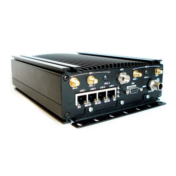
3 Components and Power Supply Alcatel-Lucent Chapter 3 Components and Power Supply The following chapter provides detailed information on the chassis of the OA5725A router family and its components. This information includes: • Components. • Information on assembly. • Power supply. - Page 11 ANT. 1 Wi-Fi. WiFi antenna for the Wireless LAN module. This module is optional; therefore it’s possible that your device doesn’t have any antennas. ANT. 1 CELL 1. Main antenna for the OA5725A cellular Module 1 (cellular10/xinterface). ANT. 1 CELL 2. Main antenna for the OA5725A cellular Module 2 (cellular11/xinterface).
-
Page 12: Mounting Options
3.2 Mounting options The OA5725A device can be mounted in various vehicles on the wall, ceiling or on a horizontal surface. The front and rear device panels have three apertures so you can add a bracket with slots to firmly hold the device. -
Page 13: Assembly: Recommendations
Access Location. If the equipment is going to be installed in a non-Restricted Access Location where untrained service personnel can access, the equipment must be mounted inside a separate compartment like a Security Lock Box OA5725A Router... -
Page 14: Outline Drawing
3 Components and Power Supply Alcatel-Lucent Security LockBox Fig. 5: 3.2.2 Outline drawing An outline drawing is provided for proper installation. Outline drawing Fig. 6: 3.3 Power Source The OA5725A router family is powered using direct current (DC). Workplace Conditions. Main Characteristics: OA5725A Router... -
Page 15: Connecting The Power Cable To The Vehicle
The power supply cable goes from the fuse panel to the router along the vehicle wall, ALWAYS inside the vehicle cabin and WITHOUT crossing the vehicle’s firewall protection. 3.3.2 Connecting the power cable to the device To terminate the cable into the connector follow the instructions below: OA5725A Router... - Page 16 • Locate the 12 - 24 V DC connector, which is found on the rear part of the device. • Insert the power cable connector. 3.3.2.2 Disconnecting • Disconnect the power supply cable from the device. • Disconnect the data cables. OA5725A Router...
-
Page 17: Cable Features
3.3.5 Configuring Power Management The OA5725A is endowed with a power management system that allows the following: - the device will only switch on when the vehicle has been switched on. - when installed, the device switches off a short time after the vehicle has been switched off, i.e. there is a slight delay with respect to the vehicle being switched off. -
Page 18: Deactivating Power Management
Access the Web probe configuration Config>set ignition-off-powerdown-timer ? <1..1440> Power down timeout in minutes disabled Disable ignition off power down timer Config>set ignition-off-powerdown-timer 10 Config> For further information on this command, please see manual ALU- Dm704-I Configuration and Monitoring. OA5725A Router... -
Page 19: Protection Fuse
The OA5725A routers have a block of 8 microswitches available that are used for maintenance and test tasks. In this case, they are only used to load the default configuration. This block of microswitches can be found inside the OA5725A routers. You need to remove the top casing in order to handle them. - Page 20 Current software license: 29 12 S/N: 777/000127 BIOS MAC Add: 00-a0-26-a4-00-1b >> ..TRYING APP CODE DUMP (CONFIGURED) APPCODE1.BIN ver.: 0.11.0.01 0.0.0.0..............................APP DATA DUMP......Running application Default configuration used Parsing text mode configuration ... Configuration parsed Initializing OA5725A Router...
-
Page 21: Reset Button
3.7.2 AUX Connector The OA5725A router family has a DB9 female connector on the front panel referred to as “ AUX.” , which can be used as a configuration port for the router or as a V.24 asynchronous serial port through a configuration command. The behavior or functionality of this interface must be previously configured. -
Page 22: Connecting To A Wwan Antenna (Cell Connectors)
CELL2, which are located on the front of the device. Antenna installation is essential in the OA5725A routers in order to improve the quality of the signal received and transmitted by the Wireless WAN module (GPRS, UMTS, HSDPA, HSUPA, HSPA+, LTE, etc.). - Page 23 In order to achieve optimum features, the installed radio frequency accessories (antennas and cables) should be those recommended by ALU. ALU has a series of accessories that allow the OA5725A routers to be installed in different locations. 3.7.3.1 Positioning the antenna The antenna orientation and its location with respect to other wireless devices and radiation devices (such as com- munication devices, personal computers, etc.) can significantly influence device performance.
-
Page 24: Connecting The Wireless Lan Antenna (Wi-Fi Connectors)
3.7.4 Connecting the Wireless LAN Antenna (Wi-Fi connectors) The OA5725A routers have two connectors to connect an external antenna which improves the quality of the signal received and transmitted through the Wireless LAN module. This module is optional; it is possible that your device does not have Wireless LAN and consequently no antennas. - Page 25 3 Components and Power Supply Alcatel-Lucent provides 3.3 V power. OA5725A Router...
-
Page 26: Chapter 4 Installing The Sim Card
Alcatel-Lucent Chapter 4 Installing the SIM card The OA5725A routers have a Wireless WAN interface, which, in order to operate, may require at least one SIM card to be inserted in the device. Certain services (CDMA) provided by some carriers in a few countries that do not require SIM cards. In installations where a SIM card is required, you must always insert at least one SIM card. -
Page 27: Identifying The Sim Trays
When there are two modules installed, the SIMs’ tray assignment is set and is as follows: • Module MD1 -> SIM #1 • Module MD2 -> SIM #2 The location of the modules and the SIM trays are shown in the following figures. SIM tray #1 for MD1 module (main) Fig. 19: OA5725A Router... -
Page 28: Installing The Sim
(4) Return the tray to its original position. (5) While pressing on the tray, push the fastening in the direction indicated by the word LOCK so it is firmly held in place. Instructions on how to insert the SIM in the internal tray Fig. 21: OA5725A Router... -
Page 29: Verizon Wireless Sim Cards
Remember that this can take up to 10 minutes and you shouldn’t either switch off nor restart the device or the LTE module. Once the provisioning process has finished, the device registers in the network and the data call establishes. OA5725A Router... -
Page 30: Appendix A Technical Information
A.2 Upgrading the software The OA5725A routers can be upgraded to new releases. Please ask your distributor for further details on new re- leases. There are several ways to upgrade one of our routers. Please read the corresponding manual on software “ALU-Dm748-I Software Updating”... -
Page 31: Connecting Through The Local Console (Aux Connector)
A.3.1 Connecting through the local console (AUX connector) The OA5725A routers have a DB9 female connector on the rear panel referred to as “ AUX.” which provides access to the device’s CLI or this can operate as an asynchronous serial port. The behavior or functionality of this interface must be previously configured. -
Page 32: Connectors
• Configure the Ethernet interface on the IP terminal (normally a PC) using the IP address from the following range [192.168.1.2, 192.168.1.254] and mask 255.255.255.0. E.g. 192.168.1.2, 255.255.255.0. • Connect the IP terminal’s Ethernet interface to any of the Ethernet Switch ports on the OA5725A router (the LAN1...4 connectors) through an Ethernet cable (RJ45). -
Page 33: Wlan Connectors
Technical Information Alcatel-Lucent A.4.3 WLAN Connectors Internal RF in/out External A.4.4 GPS Connector Internal RF in/out External A.4.5 AUX Connector CONF DB9 CONFIGURATION A.4.6 POWER Supply Connector SIGNAL BATTERY / VCC ACC / IGNITION A.5 Technical Specifications OA5725A Router... -
Page 34: Architecture Hardware
Depends on the type of wireless WAN. Please see the manual on the antennas for Cellular interfaces. A.5.4 Independent GPS Interface STANDARDS NIMEA TECHNOLOGY SiRF® star IV FREQUENCY 1.575,42 MHz CONNECTOR RF FME Male ANTENNA Active 3.3 V max 80 mA OA5725A Router... -
Page 35: Wireless Lan Interface
V.24 DCE only 8-N-1, without flow control. PROTOCOLS Asynchronous Port: AT, PPP, GPS-DATA SPEED Asynchronous Port: 300 to 115.200 bps Local Console: 9.600 bps (configurable up to 115.200) CONNECTOR DB9 female, on the front panel of the device. OA5725A Router... -
Page 36: Power Supply
LENGTH x WIDTH x HEIGHT 238 x 165 x 62 mm WEIGHT 0.9 kg A.5.9 Environmental Specifications TEMPERATURE Operating: -25 ºC to 70 ºC RELATIVE HUMIDITY ON: 8 % to 85 %. (“non condensing”) OFF: 5 % to 90 %. (“non condensing”) OA5725A Router... -
Page 37: Appendix B Regulatory Compliance And Safety Information
B.1 Recycling and the Environment Please do not, under any circumstances, throw away any OA5725A with normal domestic waste. Ask your local town hall for information on how to correctly dispose of them in order to protect the environment against e-waste. Always respect the current laws regarding waste material. -
Page 38: B.2 Translated Safety Warnings
Regulatory compliance and safety information Alcatel-Lucent B.2 Translated Safety Warnings OA5725A Router... - Page 39 Regulatory compliance and safety information Alcatel-Lucent Connecting Disconnecting OA5725A Router...
- Page 40 Regulatory compliance and safety information Alcatel-Lucent OA5725A Router...
- Page 41 Regulatory compliance and safety information Alcatel-Lucent OA5725A Router...
-
Page 42: Translated Safety Warnings
FCC Rules. These limits are designed to provide reasonable protection against harmful interference when the equipment is operated in a commercial environment. This equipment generates, uses, and can radiate radio frequency energy and, if not installed and used in accordance OA5725A Router... - Page 43 “Digital Apparatus,” ICES-003 of the Department of Commu- nications. Cet appareil numérique respecte les limites de bruits radioélectriques applicables aux appareils numériques de Classe A prescrites dans la norme sur le matériel brouilleur: “Appareils Numériques, ” NMB-003 édictée par le ministère des Communications. OA5725A Router...
Need help?
Do you have a question about the OA5725A and is the answer not in the manual?
Questions and answers